In software engineering, a class diagram in the Unified Modeling Language (UML) is a type of static structure diagram that describes the structure of a system by showing the system's classes, their attributes, operations (or methods), and the relationships among objects. The classes in a class diagram represent both the main elements, interactions in the application, and the classes to be programmed.
In the diagram, classes are represented with boxes that contain three compartments:
- The top compartment contains the name of the class. It is printed in bold and centered, and the first letter is capitalized.
- The middle compartment contains the attributes of the class. They are left-aligned and the first letter is lowercase.
- The bottom compartment contains the operations the class can execute. They are also left-aligned and the first letter is lowercase.
To specify the visibility of a class member (i.e. any attribute or method), these notations must be placed before the member's name:
| Acces modifier | Meaning |
|---|---|
| + | Public |
| - | Private |
| # | Protected |
| ~ | Package |
This association relationship indicates that (at least) one of the two related classes make reference to the other. This relationship is usually described as "A has a B" (a mother cat has kittens, kittens have a mother cat).
| Example | Meaning |
|---|---|
| 0 | No instances (rare) |
| 0..1 | No instances, or one instance |
| 1 | Exactly one instance |
| 1..1 | Exactly one instance |
| 0..* | Zero or more instances |
| * | Zero or more instances |
| 1..* | One or more instances |

A relationship is a general term covering the specific types of logical connections found on class diagrams. A Link is the basic relationship among objects. It is represented as a line connecting two or more object boxes.
If two classes in a model need to communicate with each other, there must be a link between them, and that can be represented by an association (connector).
Association can be represented by a line between these classes with an arrow indicating the navigation direction. In case an arrow is on both sides, the association is known as a bidirectional association.
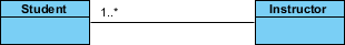
We can indicate the multiplicity of an association by adding multiplicity adornments to the line denoting the association. The example indicates that a Student has one or more Instructors:
A single student can associate with multiple teachers:

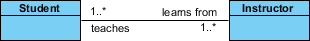
The example indicates that every Instructor has one or more Students:
We can also indicate the behavior of an object in an association (i.e., the role of an object) using role names:
Aggregation and Composition are subsets of association meaning they are specific cases of association. In both aggregation and composition object of one class "owns" object of another class. But there is a subtle difference:
Aggregation - an association that represents a part-whole or part-of relationship. Aggregation implies a relationship where the child can exist independently of the parent. Example: Class (parent) and Student (child). Delete the Class and the Students still exist.
Composition implies a relationship where the child cannot exist independent of the parent. Example: House (parent) and Room (child). Rooms don't exist separate to a House.
It indicates that one of the two related classes (the subclass) is considered to be a specialized form of the other (the super type) and the superclass is considered a Generalization of the subclass. In practice, this means that any instance of the subtype is also an instance of the superclass. An exemplary tree of generalizations of this form is found in biological classification: humans are a subclass of simian, which is a subclass of mammal, and so on. The relationship is most easily understood by the phrase 'an A is a B' (a human is a mammal, a mammal is an animal).
The UML graphical representation of a Generalization is a hollow triangle shape on the superclass end of the line (or tree of lines) that connects it to one or more subtypes. The generalization relationship is also known as the inheritance or "is a" relationship.
The superclass (base class) in the generalization relationship is also known as the "parent", superclass, base class, or base type.
The subtype in the specialization relationship is also known as the "child", subclass, derived class, derived type, inheriting class, or inheriting type.
For Example, a Bank Account is of two types - Savings Account and Credit Card Account. Savings Account and Credit Card Account inherit the common/ generalized properties like Account Number, Account Balance, etc. from a Bank Account and also have their specialized properties like unsettled payment etc.

Dependency - a relationship in which one element, the client, uses or depends on another element, the supplier
A dependency is a semantic connection between dependent and independent model elements. It exists between two elements if changes to the definition of one element (the server or target) may cause changes to the other (the client or source). This association is uni-directional. A dependency is displayed as a dashed line with an open arrow that points from the client to the supplier.
Strictly speaking, A depends on B is changes to B might necessitate changes to A. This is a bit stronger than UML dependency because it implies transitivity.
A better reading is A depends on B if A references B. This is a bit too weak because A might reference B in some implicit way.
Perhaps the simplest way around this is to say A depends on B is that A uses B. \
Examples:
The gui package might contain a class such as CustomerView that depends on the Customer class, which belongs to the business package. We also say that gui imports from business or that business exports to gui.
The CustomerView class may have a method called display that expects a Customer object as input:
class CustomerView { void display(Customer c) { ... } ... }
A CustomerView object may contain a pointer to a Customer object.
In UML modelling, a realization relationship is a relationship between two model elements, in which one model element (the client) realizes (implements or executes) the behavior that the other model element (the supplier) specifies.
The UML graphical representation of a Realization is a hollow triangle shape on the interface end of the dashed line (or tree of lines) that connects it to one or more implementers. A plain arrow head is used on the interface end of the dashed line that connects it to its users. In component diagrams, the ball-and-socket graphic convention is used (implementors expose a ball or lollipop, whereas users show a socket). Realizations can only be shown on class or component diagrams. A realization is a relationship between classes, interfaces, components and packages that connects a client element with a supplier element. A realization relationship between classes/components and interfaces shows that the class/component realizes the operations offered by the interface.