STM prescaler (clock SPI) #55
-
|
Hi! |
Beta Was this translation helpful? Give feedback.
Replies: 2 comments
-
|
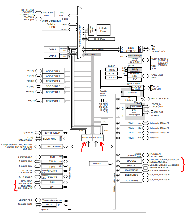
The prescaler serves to divide the clock frequency sourced to the SPI peripheral in order to achieve the desired frequency transmission during the communication. First, we start finding which is the frequency of the clock signal sourced to the SPI peripheral. From the datasheet of the STM32F401RE (page 14) we can see that SPI peripherals use the clock APB1 or APB2 (depending on the SPI peripheral used). For example, SPI2 uses APB1.
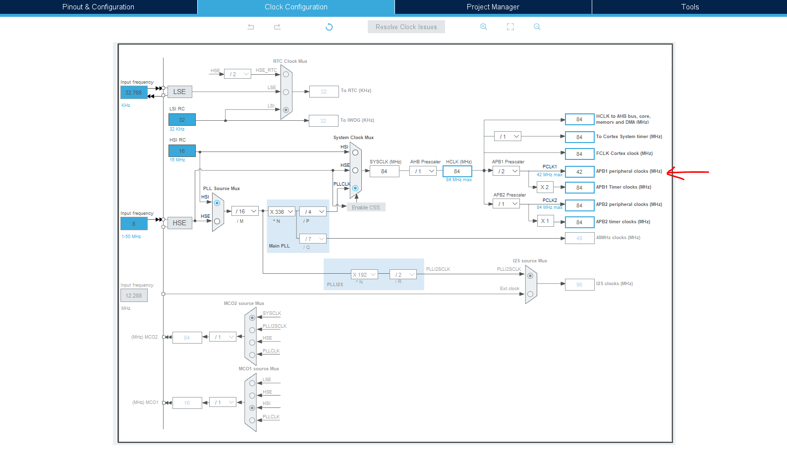
Then, we can go to the STM32CubeIDE and check which frequency is configured for the APB2. We can see that is configured with 42 MHz.
If we want a frequency transmission equal to the example in the other issue (500 kHz), we obtain a prescaler equal to 84. We have 84 available as prescaler? No. We can use 64 (frequency transmission equal to 656.25 kHz) or 128 (frequency transmission equal to 328,125). You can choose either of the two as the obtained frequencies are in the frequency range compatible with the sensor.
|
Beta Was this translation helpful? Give feedback.
-
|
Ok! Thank you |
Beta Was this translation helpful? Give feedback.
The prescaler serves to divide the clock frequency sourced to the SPI peripheral in order to achieve the desired frequency transmission during the communication.
First, we start finding which is the frequency of the clock signal sourced to the SPI peripheral. From the datasheet of the STM32F401RE (page 14) we can see that SPI peripherals use the clock APB1 or APB2 (depending on the SPI peripheral used). For example, SPI2 uses APB1.
Then, we can go to the STM32CubeIDE and check which frequency is configured for the APB2. We can see that is configured with 42 MHz.
If we want a frequency transmission equal to the example in the other issue (500 kHz), we obtain a prescaler equal to 84. We h…