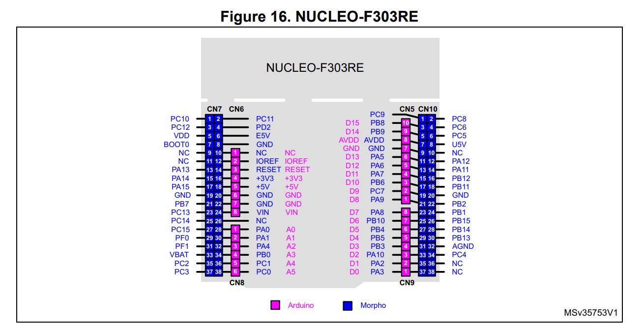
Slave SPI Interface (to host microprocessor)
| Pin Name | STM32 Pin | Description |
|---|---|---|
| CS_Slave | PB12 | Chip select signal. Bring low to select the iSensor-SPI-Buffer for communications. This pin is an input for the iSensor-SPI-Buffer |
| SCLK_Slave | PB13 | SPI clock signal. This pin is an input for the iSensor-SPI-Buffer |
| MISO_Slave | PB14 | Master in slave out (MISO) signal. This pin is an output from the iSensor-SPI-Buffer |
| MOSI_Slave | PB15 | Master out slave in (MOSI) signal. This pin is an input for the iSensor-SPI-Buffer |
Master SPI Interface (to IMU)
| Pin Name | STM32 Pin | Description |
|---|---|---|
| CS_Master | PA4 | Chip select signal, used to enable the IMU slave SPI interface. This pin is an output from the iSensor-SPI-Buffer |
| SCLK_Master | PA5 | SPI clock signal. This pin is an output from the iSensor-SPI-Buffer |
| MISO_Master | PA6 | Master in slave out (MISO) signal. This pin is an input for the iSensor-SPI-Buffer |
| MOSI_Master | PA7 | Master out slave in (MOSI) signal. This pin is an output from the iSensor-SPI-Buffer |
The IMU reset pin is mapped to PA3 (hardware rev C or newer)
SPI 3 (master to communicate with SD card/etc)
| Pin Name | STM32 Pin | Description |
|---|---|---|
| CS_SD | PA15 | Chip select signal |
| SCLK_SD | PC10 | SPI clock signal |
| MISO_SD | PC11 | Master in slave out (MISO) signal |
| MOSI_SD | PC12 | Master out slave in (MOSI) signal |
SW_SD (SD card detect line) is mapped to PD2
DIO / ADG1611 Control
| Pin Name | STM32 Pin | Description |
|---|---|---|
| DIO1_Master | PB5 | DIO1 input signal from IMU to iSensor-SPI-Buffer |
| DIO2_Master | PB9 | DIO2 input signal from IMU to iSensor-SPI-Buffer |
| DIO3_Master | PC6 | DIO3 input signal from IMU to iSensor-SPI-Buffer |
| DIO4_Master | PA9 | DIO4 input signal from IMU to iSensor-SPI-Buffer |
| DIO1_Slave | PB4 | DIO1 output signal from iSensor-SPI-Buffer to master |
| DIO2_Slave | PB8 | DIO2 output signal from iSensor-SPI-Buffer to master |
| DIO3_Slave | PC7 | DIO3 output signal from iSensor-SPI-Buffer to master |
| DIO4_Slave | PA8 | DIO4 output signal from iSensor-SPI-Buffer to master |
| SW_IN1 | PB6 | Switch control from iSensor-SPI-Buffer. If set DIO1 will be directly passed from master to IMU |
| SW_IN2 | PB7 | Switch control from iSensor-SPI-Buffer. If set DIO2 will be directly passed from master to IMU |
| SW_IN3 | PC8 | Switch control from iSensor-SPI-Buffer. If set DIO3 will be directly passed from master to IMU |
| SW_IN4 | PC9 | Switch control from iSensor-SPI-Buffer. If set DIO4 will be directly passed from master to IMU |
LED Control
| Pin Name | STM32 Pin | Description |
|---|---|---|
| LED_RED | PC0 | Output signal from iSensor-SPI-Buffer which drives a red LED |
| LED_GREEN | PC1 | Output signal from iSensor-SPI-Buffer which drives a green LED |
ID Pins
| Pin Name | STM32 Pin | Description |
|---|---|---|
| ID0 | PC2 | Identifier pin 0. These pins can be populated with a pull up/down to differentiate between different hardware configurations (e.g. SD card, etc) |
| ID1 | PC3 | Identifier pin 1 |
