The Arduino Uno used so far in this tutorial does not have WiFi capabilities and therefore cannot connect to the Internet. The following example uses a different microcontroller: the ESP8266. This microcontroller features a WiFi module that allows it to connect to the Internet and to communicate with remote servers. This tutorial uses a service called IFTTT. IFTTT is a free web-based cloud service used to create chains of simple conditional statements. The IFTTT service is popular among home automation and DIY projects. IFTTT also offers free Android and iOS apps for download that are used in this tutorial. The diagram below depicts the overall architecture:

The ESP8266 uses its built-in WiFi module to connect to a local WiFi router. The sketch running on the ESP8266 performs an HTTP POST request to a remote IFTTT server. That POST request contains a unique key that identifies a specific user. IFTTT uses this key to send a push-notification to the user's mobile device. The benefit of using IFTTT is that it requires no programming on the server- or mobile-side. Programming the ESP8266 is more complicated than programming an Arduino Uno. The following sections discuss the complete setup step-by-step.
The ESP8266 does not have an USB interface. In order to flash compiled sketches to the ESP8266, a so-called FTDI adapter needs to be used that converts USB to a serial signal. The ESP8266 is connected to the RXD/TXD (receive/transmit) pins of the FTDI adapter. The following diagram shows the pinout of the ESP8266:
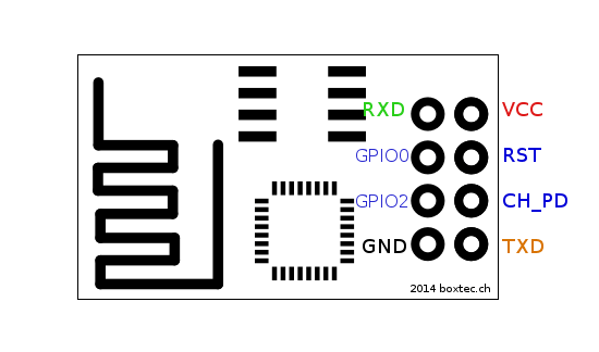
Note that the ESP8266 operates on 3.3V and the jumper on the FTDI adapter needs to be set accordingly. Powering the ESP8266 with 5V will destroy it. The following wiring shows how the FTDI adapter is connected to the ESP8266:

A few notes on the wiring:
- The color of the wires have no relevance.
- The wiring as shown would require female-to-female cables that are not part of the Arduino starter kit. The FTDI adapter can be plugged in to the breadboard. Use the breakout board for the ESP8266. Then use the regular male-to-male cables to make the connections on the breadboard.
- The sequence of pins for the FTDI adapter shown in the wiring diagram is different from the actual FTDI adapter used for this tutorial. Make sure to make the correct connections, e.g., the ESP8266's RXD pin needs to be connected to the FTDI adapter's TXD pin, etc.
- The two buttons are used to put the ESP8266 into flash mode as explained below. The flash button is connected to the ESP8266 pin 0 and can also be used by a sketch for other purposes.
The wiring features two buttons: a reset and a flash button. The reset button causes the ESP8266 to reboot. The flash button is connected to GPIO pin 0. When the ESP8266 reboots, it will enter flashing mode when this pin is asserted to low. In order to upload a new sketch to the ESP8266, the following procedure is necessary: press the flash button and keep it pressed while also pressing the reset button. The ESP8266 will reboot and the reset button can be released. Keep the flash button pressed for a few more seconds while the ESP8266 boots. Once the ESP8266 is in flashing mode, a new sketch can be uploaded via the Arduino IDE.
The standard Arduino IDE can be used to program and upload a sketch to the ESP8266. To add support for the ESP8266, the following needs to be done once:
- In the Arduino IDE, go to the Preferences dialog.
- In the "Additional Board Manager URLs" field, enter the following URL:
http://arduino.esp8266.com/stable/package_esp8266com_index.json. Multiple URLs in that field need to be comma-separated.

- After clicking OK, go to Tools > Board > Boards Manager. Scroll down, select and install the "esp8266" platform published by
the ESP8266 Community.

- Select board Tools > Board > Generic ESP8266 Module. Note that no programmer needs to be selected.
- Select port Tools > Port. It might be necessary to install a USB driver to recognize the FTDI adapter which is available at ftdichip.com.


In order to use IFTTT, a user account with some additional setup is required. The IFTTT web interface is powerful, but also not always intuitive to use. The following is a step-by-step instruction on the required setup:
- Create an account at IFTTT.com
- Connect to Webhooks. Click on "Connect".

- On the top of the page, click on "My Applets".

- Click on "New Applet".

- Click on "this".

- In the search box, search for and click on "Webhooks".

- On the next page click on "Receive a web request".

- Enter "esp8266_triggered" as the Event Name. Click on "Create trigger".

- Click on "that".

- On the "Choose action service" search for "Notifications" service and Click on "Notifications".

- Click on "Connect".

- Click on "Send a notification from the IFTTT app" on the next page.

- In the text box "Notification" replace the text with the following:
{{EventName}} occurred at {{OccurredAt}}

- Click on "Create action".
- On the next page click "Finish".

- Go to the Webhook Settings page.
- On that page there is a URL that begins with
https://maker.ifttt.com/use/. What follows in the URL is the IFTTT API key. The API key identifies the user who created that key. In the following this key is referred to asAPI_KEY.

- If you are running on a Unix system you can now try to trigger an event from the command line via:
curl -X POST https://maker.ifttt.com/trigger/esp8266_triggered/with/key/API_KEY


The curl command will issue an HTTPS request to the given URL. The IFTTT server identifies a user by the
API_KEY and will send a push notification to the user's mobile device. For this to happen, the user must
have installed the (free) IFTTT app for Android or iOS and be logged in to IFTTT on the mobile device.

The
ESP8266_IFTTT
sketch is printed in its entirety below and demonstrates how to perform the POST request to the
IFTTT server. Conceptually, the sketch does the same as the curl script mentioned above. Whenever the
flash button is pressed, the ESP8266 will perform a POST request and thereby trigger a push-notification
to the user's mobile device. Note that the flash button is connected to GPIO pin 0 and can therefore be
used as input in any sketch.
There are three variables in the sketch below that need to be customized before compiling and uploading to the ESP8266:
ssid: the SSID of the WiFi network that the ESP8266 should connect to.password: the WiFi password.iftttApiKey: the IFTTTAPI_KEYas explained in the previous section.
The sketch first connects to the configured WiFi in setup() and setups up pin 0 as input. The
loop() function checks if the button attached to pin 0 (the flash button) is pressed and will
then call function doPOST() to perform the actual POST request to the IFTTT server. Note that the
sketch does not use a dedicated HTTP library. The sketch communicates to the IFTTT server by using
a plain TCP connection and by sending the
HTTP protocol
that is constructed via method client.print().

#include <ESP8266WiFi.h>
#include <WiFiClientSecure.h>

// The following three parameters need to be changed
const char* ssid = "IoT Workshop";
const char* password = "B9LZd73yWx33";
const char* iftttApiKey = "API_KEY";

const char* host = "maker.ifttt.com";
const int httpsPort = 443;

const int PIN_BUTTON = 0;

void setup() {
  Serial.begin(115200);

  WiFi.begin(ssid, password);
  while (WiFi.status() != WL_CONNECTED) {
    delay(500);
  }
  Serial.print("WiFi connected with IP address: ");
  Serial.println(WiFi.localIP());

  pinMode(PIN_BUTTON, INPUT_PULLUP);
}

void doPOST() {
  WiFiClientSecure client;
  Serial.println("Connecting to IFTTT server");
  if (!client.connect(host, httpsPort)) {
    Serial.println("Connection failed");
    return;
  }

  String url = "/trigger/esp8266_triggered/with/key/";
  client.print(String("POST ") + url + iftttApiKey + " HTTP/1.1\r\n" +
               "Host: " + host + "\r\n" +
               "User-Agent: ESP8266\r\n" +
               "Connection: close\r\n\r\n");

  while (client.connected()) {
    // Read response from IFTTT but ignore it
    String line = client.readStringUntil('\n');
    Serial.println(line);
  }
}

bool isButtonPressed() {
  return digitalRead(PIN_BUTTON) == LOW;
}

void loop() {
  if (isButtonPressed()) {
    doPOST();
    while (isButtonPressed()) ;
  }
}