Download "RASPBIAN JESSIE LITE" https://www.raspberrypi.org/downloads/raspbian/
Create your new hard disk for DashboardPI
Insert the microSD to your computer via USB adapter and create the disk image using the
ddcommandLocate your inserted microSD card via the
df -hcommand, unmount it and create the disk image with the disk copyddcommand$
df -h/dev/sdb1 7.4G 32K 7.4G 1% /media/XXX/1234-5678$
umount /dev/sdb1Caution: be sure the command is completely accurate, you can damage other disks with this command
if=location of RASPBIAN JESSIE LITE image file of=location of your microSD card
$
sudo dd bs=4M if=/path/to/raspbian-jessie-lite.img of=/dev/sdb(note: in this case, it's /dev/sdb, /dev/sdb1 was an existing factory partition on the microSD)
Setting up your RaspberriPi
Insert your new microSD card to the raspberrypi and power it on with a monitor connected to the HDMI port
Login
user: pi pass: raspberry
Change your account password for security
sudo passwd pi
Enable RaspberriPi Advanced Options
sudo raspi-config
Choose:
1 Expand File System
9 Advanced Options
A2 Hostnamechange it to "EnvironmentClock"
A4 SSHEnable SSH Server
A7 I2CEnable i2c interface
Enable the English/US Keyboard
sudo nano /etc/default/keyboard
Change the following line:
XKBLAYOUT="us"
Reboot PI for Keyboard layout changes / file system resizing to take effect
$
sudo shutdown -r now
Auto-Connect to your WiFi
sudo nano /etc/wpa_supplicant/wpa_supplicant.conf
Add the following lines to have your raspberrypi automatically connect to your home WiFi (if your wireless network is named "linksys" for example, in the following example)
network={
   ssid="linksys"
   psk="WIRELESS PASSWORD HERE"
}
Reboot PI to connect to WiFi network
$
sudo shutdown -r nowNow that your PI is finally on the local network, you can login remotely to it via SSH. But first you need to get the IP address it currently has.
$
ifconfigLook for "inet addr: 192.168.XXX.XXX" in the following command's output for your PI's IP Address
Go to another machine and login to your raspberrypi via ssh
$
ssh [email protected]
Start Installing required packages
$
sudo apt-get update$
sudo apt-get upgrade$
sudo apt-get install vim git python-requests python-smbus i2c-tools python-imaging python-smbus build-essential python-dev rpi.gpio python3 python3-pip libi2c-dev
Update local timezone settings
$
sudo dpkg-reconfigure tzdata
select your timezone using the interface
Setup the simple directory l command [optional]
$
vi ~/.bashrcadd the following line:
$
alias l='ls -lh'$
source ~/.bashrc
Fix VIM default syntax highlighting [optional]
$
sudo vi /etc/vim/vimrcuncomment the following line:
syntax on
Clone Clock repository
$
cd ~$
git clone https://github.com/khinds10/EnvironmentClock.git
Install i2c Backpack Python Drivers
$
cd ~$
git clone https://github.com/adafruit/Adafruit_Python_LED_Backpack$
cd Adafruit_Python_LED_Backpack/$
sudo python setup.py install
DHT11 Install
$
cd ~$
git clone https://github.com/adafruit/Adafruit_Python_DHT.git$
cd Adafruit_Python_DHT/$
sudo python setup.py install$
sudo python ez_setup.py$
cd examples/$
vi simpletest.py
Change the following line:
sensor = Adafruit_DHT.DHT11
Comment the line out
pin = 'P8_11'
Uncomment the line and change the pin number to 16
pin = 16
Run the test
python simpletest.py
You should see a metric reading of Temp and Humidity displayed on the command line.
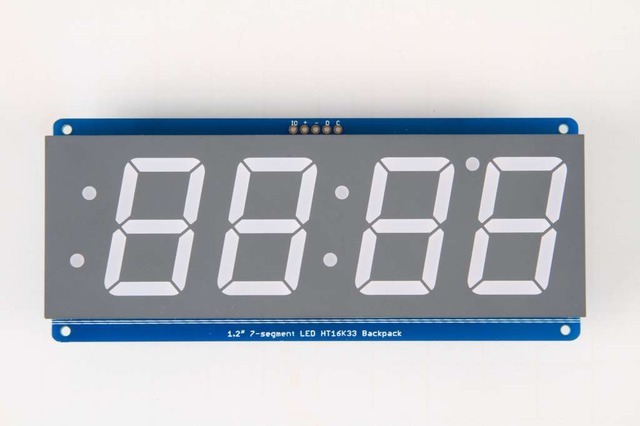
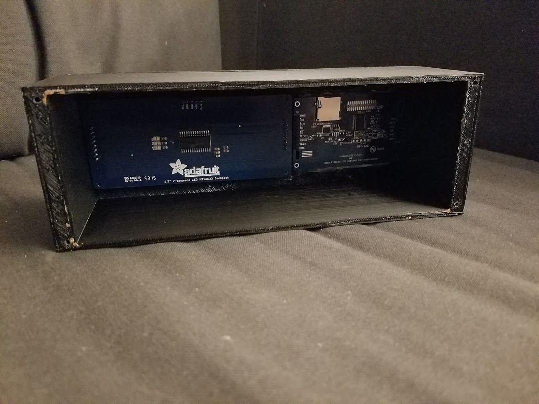
1.2 inch LED Display
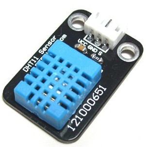
DHT11 Humidistat
2.6" Digole Display
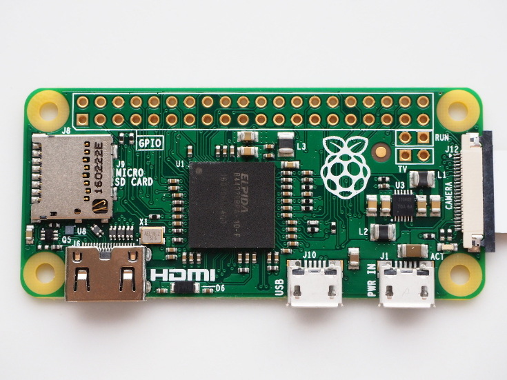
RaspberriPi Zero (or Regular RaspberriPi should work)
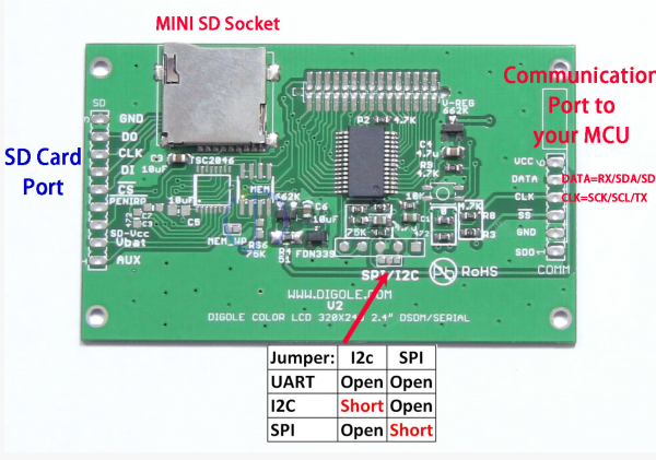
1) Prepare the Digole Display for i2C
On the back of the Digole Display, solder the jumper to assign the display to use the i2c protocol
2) Print the Project Enclosure
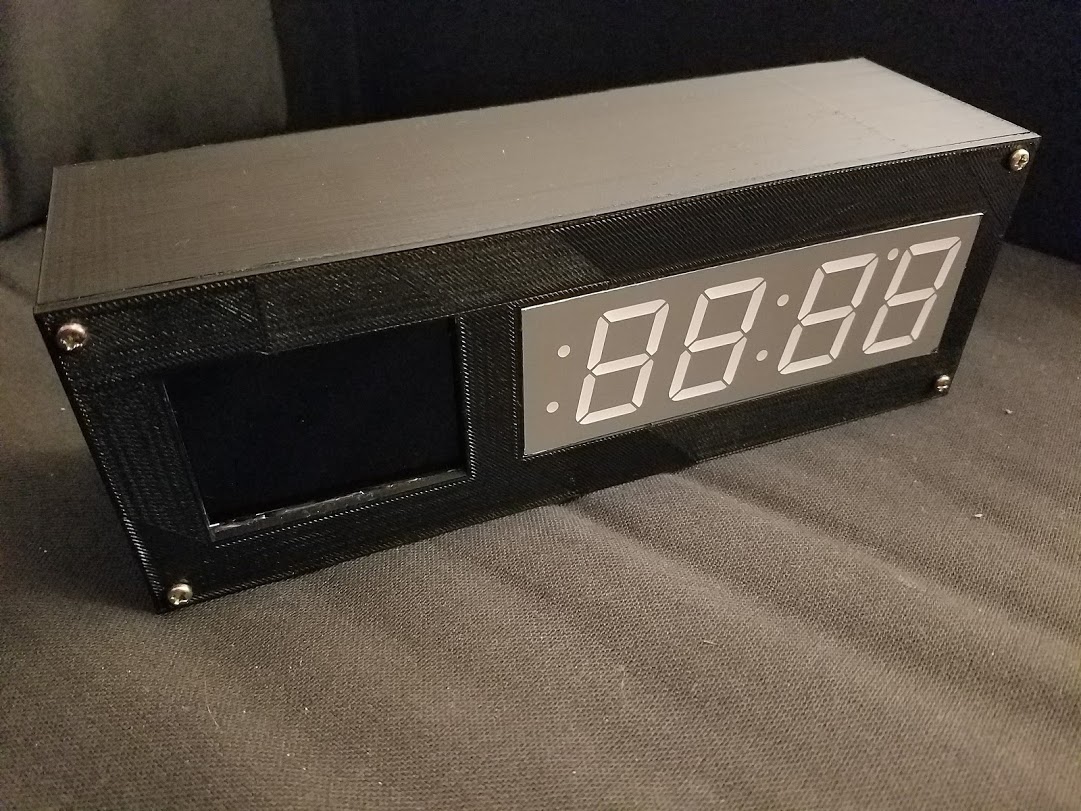
Using a 3D printer print the enclosure files included in the 'enclosure/' folder. .x3g files are MakerBot compatible. You can also use the .stl and .blend (Blender Program) files to edit and create your own improvements to the design.
3) Using 4 screws drill and attach the front panel (with the 2 holes) to the 4 sided body. Then fit the displays in each of the holes.
4) Attach the 7 segment and Digole Display using hot glue gun to hold them in place.
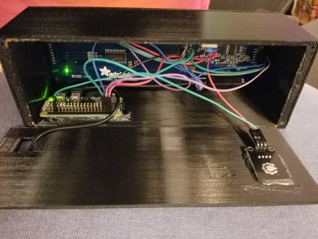
5) Prepare the wires for connection. I use standard jumping wires and a wire cutter to strip the wire bare in the middle of the wires so I can have a bunch connected together glued with a hot glue gun. (In the image below is my grouped together 5V / GND / SCA / and SCL wires.)
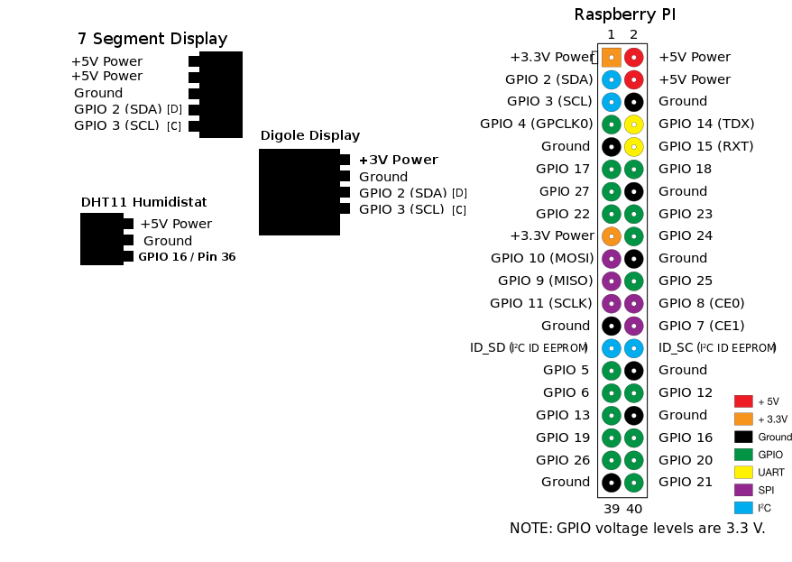
6) Begin wiring the unit using the wiring diagram below as a guide.
The 7 Segment display
D -> SDA
C -> SCL
+ -> 5v
GND -> GND
IO -> 5v
Digole Display
GND -> GND
DATA -> SDA
CLK -> SCL
VCC -> 3V
DHT11 Humidistat
VCC -> 5V
GND -> GND
DATA -> GPIO 16 / PIN 36
7) Glue the humidistat to the back panel, and run a USB cable through the other back panel hole to power the unit. Attach the back with only 2 screws in case you need to disassemble for repair.
Find the file settings.py and adjust to your current settings
# forecast.io API key for local weather information
weatherAPIURL = 'https://api.forecast.io/forecast/'
weatherAPIKey = 'YOUR API KEY FOR FORECAST.IO'
# optional for running the remote temp/humidity logger
deviceLoggerAPI = 'mydevicelogger.com'
# search google to get the Latitude/Longitude for your home location
latitude = 41.4552578
longitude = -72.1665444
$
crontab -e
Add the following lines:
@reboot nohup python /home/pi/EnvironmentClock/clock.py >/dev/null 2>&1
@reboot nohup python /home/pi/EnvironmentClock/display.py >/dev/null 2>&1
Verify the display starts working on reboot
$
sudo reboot
$
crontab -e
Add the following lines:
*/10 * * * * python /home/pi/EnvironmentClock/temp-check.py
Upload your own 128x128 file to the following URL:
http://www.digole.com/tools/PicturetoC_Hex_converter.php
Choose your image file to upload, add what size you want it to be on the screen (Width/Height)
Select "256 Color for Color OLED/LCD(1 byte/pixel)" in the "Used for" dropdown
Obtain the hex output.
Add the hex output to a display/build/ header (.h) file, use the other ones as guides for syntax.
Include the new file in the digole.c file
#include "myimage.h
Include a new command line hook to your image file in the. Note: the command below is saying draw your image at position 10 pixels over 10 pixels down. You can change it to different X,Y coordinates, you can also change the values 128,128 to whatever size your new image actually is.
} else if (strcmp(digoleCommand, "myimage") == 0) {
drawBitmap256(10, 10, 128, 128, &myimageVariableHere,0); // myimageVariableHere is defined in your (.h) file
}
Now rebuild (ignore the errors) below to have your new image render with the following command.
$
./digole myimage
Re-Building [Included] Digole Display Driver for your optional changes
$
cd display/build
$
gcc digole.c
$
mv a.out ../../digole
$
chmod +x ../../digole

