Slowing down a bit (Part 4)
The CPU of original ZX Spectrum can execute somewhere between 400-800 thousands of instructions per second. The code written in previous parts needs only few instructions for every "tick" of the game loop, leveraging the HW Sprites rendering of ZX Spectrum Next. Even at original speed of the CPU (3.5MHz) such game would be too fast to be played by humans (and we could still raise the CPU speed of Next to 7, 14 or 28 MHz).
So we need to slow it down a lot to make it playable.
One of the possibilities is to run empty loops just burning the CPU time, if we add enough of these, the game will become slow enough to be playable. That's a very simple approach and many people use it in their beginnings of assembly programming. But the price for the simplicity will soon become visible.
If we will check back the screenshot in Part 3, and look closely at the snowballs, we can see some of them being torn in halves, each half having different horizontal position. Why?
Let's assume our Next is in 50Hz video mode, that means it does provide 50 new video images to the display every second (even when there is no change between two of them and the CPU is idling in infinite loop). The video signal is being generated independently on the SW, each "frame" (single image sent to the display) taking 20 milliseconds (50 frames * 20ms = 1000 ms = 1 second). And those 20ms are spent on sending the huge amount of pixel data, quite linearly, we can imagine it as invisible beam going for every line from left to right and then advancing to line below, returning to the left edge and going again from left to right, sending color of each pixel one by one to the display. When all lines are sent, the invisible beam returns back to the top and it will reach the starting point right after that 20ms time, so it will just continue its infinite path across the display, sending one more frame of pixel data.
And that's mental model how old CRT (Cathode Ray Tube) displays work, there is literally electron-beam shooting the display shield with stream of electrons, causing the particular dot of display to glow and emit light for tiny fraction of time. The more electrons the beam sends, the more "white" the pixel becomes and with less electrons the pixel seems more "black" to the human eye observing the display from outside. The movement of the electron beam across the display is done by strong electromagnets, bending the original trajectory of electron shot straight at the centre of screen toward different spot of the display (when the electromagnets stopped working due to some malfunction and you have seen only single very bright dot in the centre of your CRT display, you had literally few seconds to switch the TV off before the display shield got burnt-out from abundance of electrons targeting the single spot). And the "returning of beam" was literally bending it back toward left/top edge of the screen (with very low level of electrons being shot during this "retrace" period, making it not visible on the display shield), i.e. resetting the polarity/power of magnets to have it ready for start of new line.
Even those "return beam" periods take some time, which is often referred to as "h-blank" and "v-blank" periods (horizontal/vertical "blank" period when no pixel data are being sent to the display).
But I hear you, why the duck are the snowballs torn and could I stop drifting away to other topics? Because the snowball is at X-position 50 while the video signal generator sends for example first half of lines where the snowball resides and just when the video signal generator starts to send second half of lines, the code uploading new sprite positions from memory to FPGA is executed, the X-position of snowball becomes 53 and the HW rendering sprites will render the second half of the ball on the new position, for the video signal generator (asking the sprite renderer for new line of data when it is building the final signal for display - it's actually asking it for data pixel by pixel, so we can race with the "beam" even at pixel level).
To get smooth non-tearing animation on computer you have to synchronize modifications of the video data against the display-beam drawing the image, providing the beam with "final" image across the 20ms (for 50Hz mode) duration span. You can for example modify image lines behind the beam and prepare next frame data there, but you need to have the "current" data of particular line ready whenever the beam starts to emitting that line to the display. If you mismatch the modifications of the image data, the human eye will see part of the image displaying the old data and part of it displaying the modified data, usually perceived as "tearing".
Now as you can read above, the h-blank and v-blank are short periods of time when there are no pixel data sent to the display, so these periods of time are frequently used by programmers to update video data to avoid any clashing with the beam. The h-blank of beam returning from right to left is actually very short period worth only couple of CPU instructions, but the v-blank period of beam returning from bottom to top of display takes often around 4-10% of total duration of frame (depending on the exact specs of the video mode), and many games with trivial game code target this period of time to finish all their errands, prepare new data in video-ram, and enter dormant state waiting for machine to generate all pixels and entering another v-blank period.
Games with more computationally-demanding logic often use the time of beam traveling through the pixel-area to calculate non-visual intermediate values into memory buffers and then do the final visual-data update in the v-blank period to be ready for next frame, or they use double-buffering scheme drawing future frame into off-screen buffer, which is made visible in one short operation after it is ready for displaying.
We want to slow down the SpecBong, but we surely want also to have smooth animations without tearing, right? So let's first synchronize with the beam sending the pixel data to the display. Every game loop we will wait for videoline 192 (right below the 256x192 pixel area of Layer2 mode, where the background image is stored), doing nothing. Then at videoline 192 (aka "scanline" in some texts) we will upload the sprite attributes data to the FPGA, positioning all 128 sprites to their new state before the beam will reach top of the display. Later we will also update other parts of the visual UI, like score, number of lives and whatever else is directly modifying the display output.
After these image-changing updates are done, the game will proceed to read the player inputs, calculate new sprite positions, and do any other logic, preparing the sprite-attributes buffer for the upload at beginning of next loop "tick".
This will ensure we will have smooth movement of elements on the screen, but it will also make our game-loop to tick at the frequency of the display mode (50 to 70 Hz depending on the video mode being used by the Next). If we will move the player by one pixel per "tick", it will thus move only 50 to 70 pixels per second, which is suddenly speed of game in human-playable range. Unfortunately it will cause the game running somewhat faster for people using video modes with higher refresh rate. Making the game logic both speed-stable and animation being pixel-smooth is very complex problem, way out of the scope of this tutorial (often solved by some compromise one way or another), so SpecBong will accept the varying game-play speed based on the video mode used (making the user experience with VGA0 50Hz mode the main target). In exchange we will have pixel-perfect-smooth-animations and simple way to slow down our game loop by simply waiting for videoline 192.
There it is, we resolved the "slowing down" part by fixing the smoothness of screen updates instead.
(here is a good spot to open the SpecBong.asm file and try to match the source code lines with this text)
(you can also check the total difference between "Part 4" and "Part 3")
The GameLoop will first call the "wait for videoline" subroutine, to sync with the position of the display beam.
And then do the same stuff as before, uploading sprite-attributes data of all sprites to FPGA, then updating the values in memory buffer with new positions.
The "wait" subroutine is added as WaitForScanlineUnderUla, it does first increment 32bit counter TotalFrames by one to keep track of how many frames were already displayed.
Then it reads NextReg $1F "Active Video Line LSB", that's the low 8 bits of videoline number (the videolines are numbered from 0 at the top edge of the 256x192 pixel area to the total-lines minus one for the line just above the 256x192 pixel area, most of the video modes of Next having around 312 lines in 50Hz or around 263 lines in 60Hz, but the precise amount differs by the machine personality and video output selected). Even the "longest" video mode reach at most value like 311. Such value needs nine bits to be encoded, with the top bit being zero for lines 0..255 and one for lines 256..311, and the bottom eight bits will reach the values 0..255 for 0..255 lines (duh!) and 0..55 for lines 256..311. This makes the task of "wait for line 192" as simple as reading only the LSB value and checking that against value 192 (if we would want to wait for video line 256, the LSB would hit value "0" twice per frame for both videoline 0 and videline 256, and we would have to read also the NextReg $1E "Active Video Line MSB" and check it for value 1 to be sure we are at videoline 256).
And that's all for the new subroutine, when the videoline 192 is detected as being "active line", it returns back to game loop to let it do the visual updates.
There's the new 32bit counter TotalFrames: DD 0 in the data area for the purpose of counting frames (reserving the memory for it).
The new frame-counter is then used by the SnowballsAI routine to alternate between sprite-patterns 52 and 53 only every 8th frame (speed of animation is then about 6.25FPS in 50Hz mode, because 50 / 8 = 6.25).
The remaining (non-comment-only) change of the source is the new line with directive CSPECTMAP "SpecBong.map" - producing the debug info for #CSpect emulator, so when we launch the emulator providing both the NEX file and the MAP file, we will see in the debugger of CSpect our labels from source code.
When you will run the NEX file on the machine now, the snowballs will fly all over the screen with smooth animation and with lot more reasonable speed.
While reviewing the resulting source code for Part 4, there were various "magic numbers" all over the place. That is usually considered bad practice, so I copied the constants.i.asm from the test-suite project and replaced all next-register and I/O port hard-coded numbers with symbolic constants, like SPRITE_CONTROL_NR_15 instead of $15.
Check the difference in source code on github
There's no functional change of the code in the Part 4B.
While working on game like SpecBong, one can wonder how much time is spent on the game loop update and where is the display beam at particular stage of update. The very simple technique used already back on original ZX Spectrum machines was to modify border color (I/O port 254) at beginning end of certain part of code. Because the video signal generator is putting color of border areas into signal in real-time, any change on port 254 is applied right at the spot where the display-beam is.
Adding setup of red border right after the WaitForScanlineUnderUla subroutine returns and switching border to magenta before calling snowballs AI will reveal with red strip in border area, how long it takes to upload sprite attributes data to the FPGA. Similarly switching border back to original blue color just before the wait for line 192 starts will reveal with the magenta strip in border how long the SnowballsAI and remaining errands take.
This creates funny situation when you are literally measuring time in distance units..
The source difference for Part 4C.
The final result looks like this:
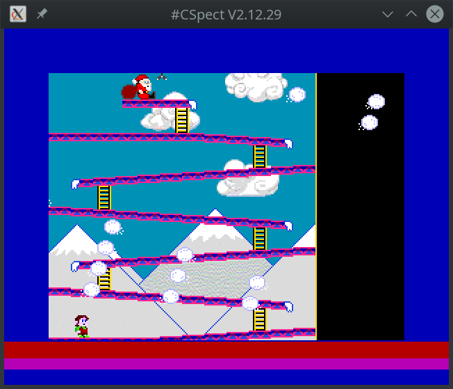
As you can see, the sprite attributes upload takes about 13 video lines of time (ca. 4% of frame in video mode with 312 lines) and the "AI" of snowballs takes about 8 video lines (ca. 2.5%). So there's about 290 (in 312 lines video mode) "spare" lines of time when the game does nothing but waits for the display beam to reach the synchronization point. That's above 90% of CPU time being used just for waiting in this version of SpecBong.
That means lot of CPU performance available for other tasks, like maybe controlling the player movements...