04. Development Reference
In this section, the user will learn how to create their own .hex files.
There are some prerequisites to make your .hex files compatible with CatSniffer:
- Download and install Code Composer Studio 12.2.0.00009
- Download and install SimpleLink CC13X2 and CC26X2 SDK 3.40.00.02.
When the installation of both software is finished, follow the next steps to build a hex file:
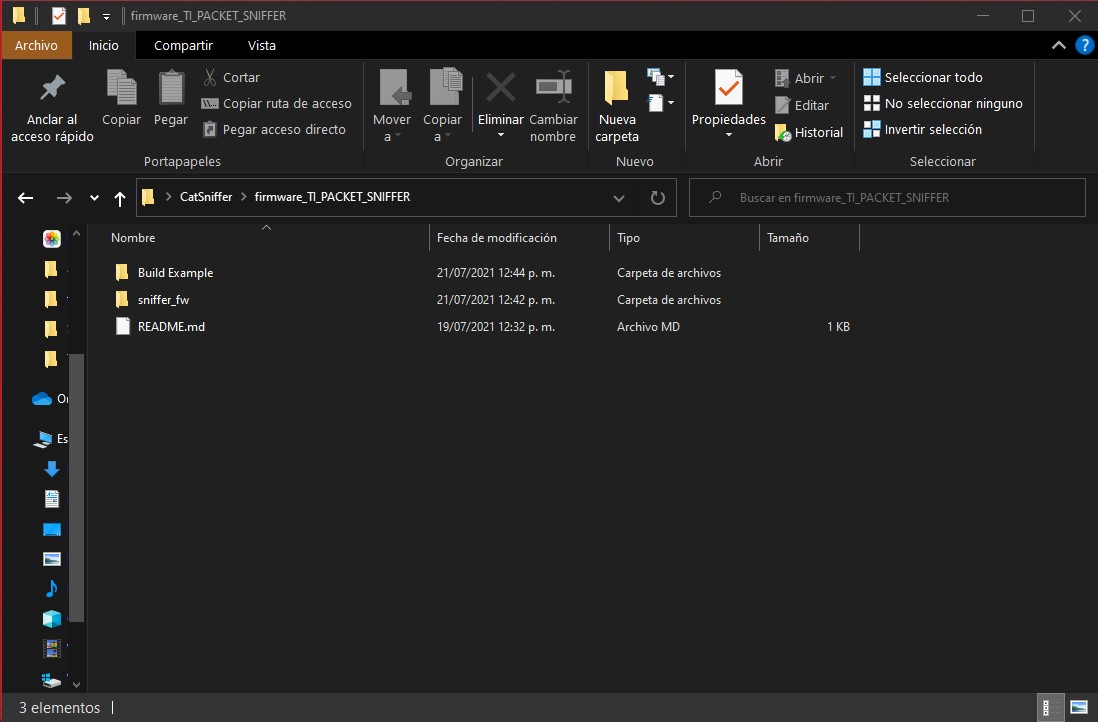
- Create a new folder inside the
firmware_TI_PACKET_SNIFFERfolder or anywhere you like. Here is an example: this new folder will be our workspace.
Create a Project Folder
- Open CCS and choose this new folder for the workspace.
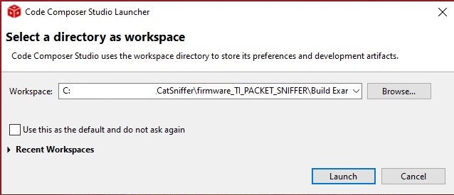
Choose the Project Folder on CCS
- When CCS runs, go to
Window > Preferences.

Preferences Location
- Now go to
Code Composer Studio > Products.

Products Location
- Select in Discovered products the SimpleLink CC13x2 26x2 SDK and press Install. Choose the path where the SDK was installed and click on Apply and Close.

Select the Correct Platform
- Now select the option Import Project; in the window, choose the option Select search-directory and browse the next path:
C:\path\CatSniffer\firmware_TI_PACKET_SNIFFER\sniffer_fw\ide\cc1352p1lp\ccs. Select the optionsniffer_fwand click on finish.

Import the Project
- When the project finishes importing, do a right click on the project
sniffer_fwand go down to properties.
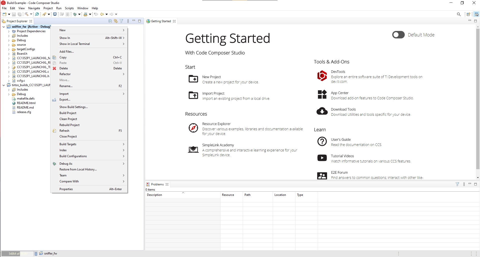
Project Properties
- In the Properties window, go to Arm Hex Utility and mark the option Enable Arm Hex Utility, and click on Apply and Close.

Enable Arm Hex Utility
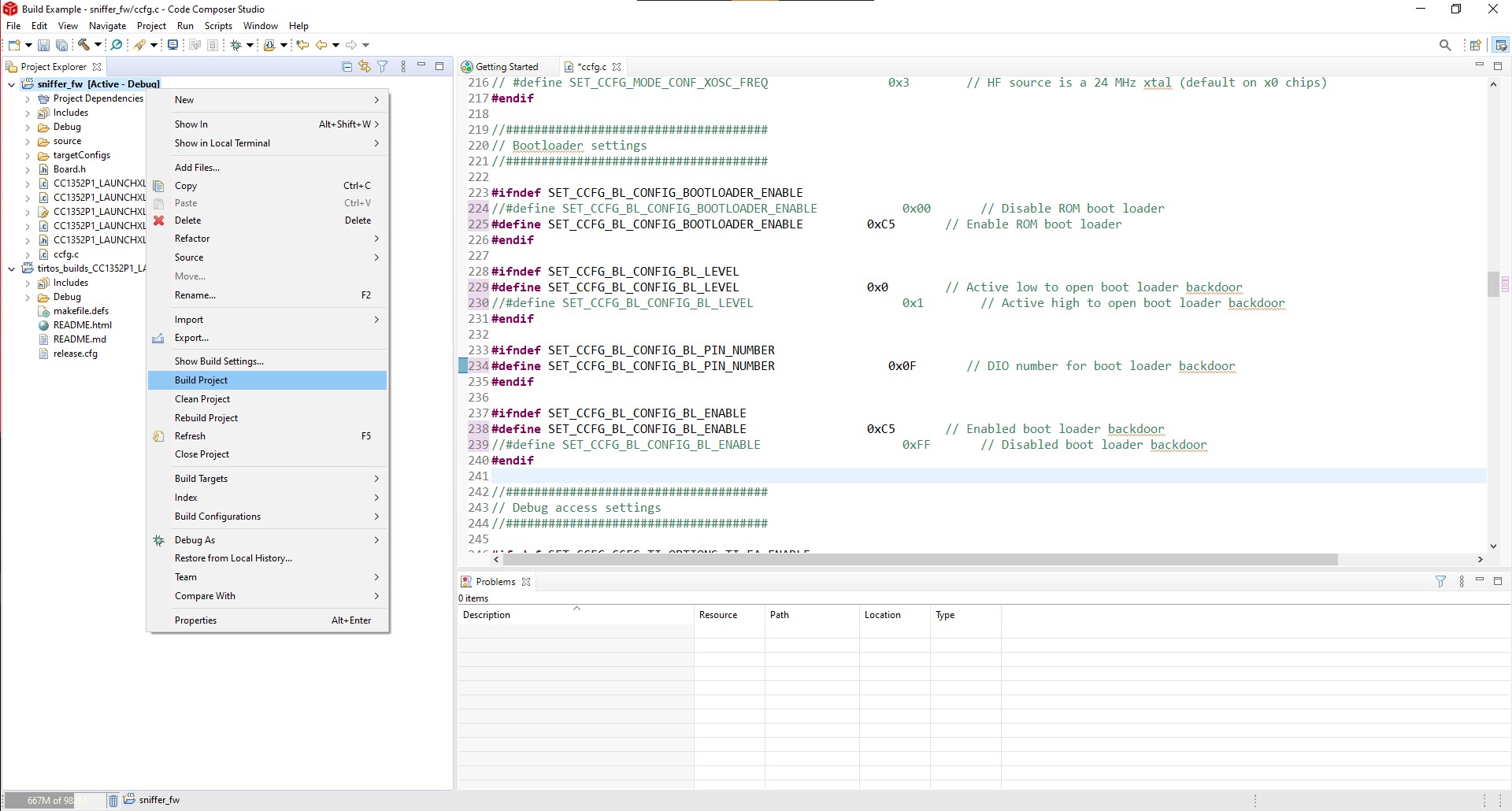
- Now go to the
ccfg.cfile and change the next values to enable the bootloader mode on CC1352:
SET_CCFG_BL_CONFIG_BOOTLOADER_ENABLE...............0xC5SET_CCFG_BL_CONFIG_BL_LEVEL.........................0x0SET_CCFG_BL_CONFIG_BL_PIN_NUMBER...................0x0FSET_CCFG_BL_CONFIG_BL_ENABLE.......................0xC5
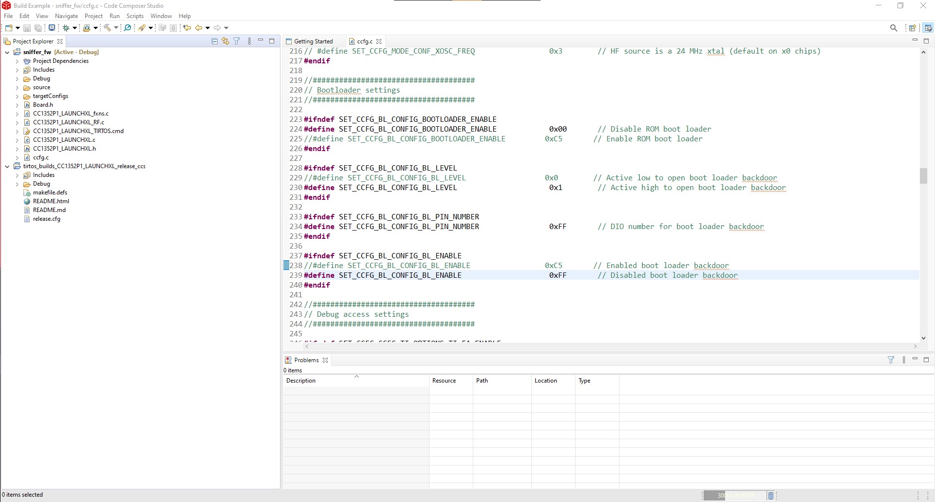
Enable Bootloader Mode
- As a way to verify the hex file, it’s recommended to activate the blink of an LED. Catsniffer's CC1352 has an LED at DIO 24, changing DIO 6 to 24 to activate LED 4. When the uploading of the hex file finishes, this LED will start blinking.
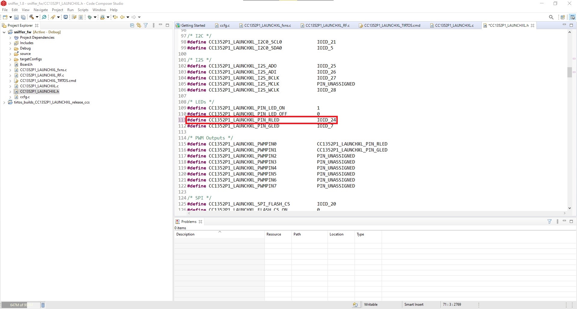
Activate LED Blink
- To build the project, do a right click on the sniffer_fw and then Build Project. and wait till it finishes.
Build Project
- The hex file will appear on the path:
C:\path\CatSniffer\firmware_TI_PACKET_SNIFFER\Build Example\sniffer_fw\Debug

Built Project on Project Folder
Now you are ready to create your own hex files and upload them to CatSniffer.
Using the free_dap_catsniffer_RP2040_v1.0.uf2 firmware, we can debug the CC1352 chip using the onboard RP2040.
For this you will need to load said firmware to your board. You can learn how to do this by going to the Uploading Firmware section of this Wiki.
Our firmware is based on the Pico Dirty JTAG project.
We start by installing OpenOCD using the command: sudo apt install openocd
We we need the following dependencies that can be installed running the command: sudo apt install git make libtool pkg-config autoconf automake texinfo
Now we need to clone the Raspberry Pi OpenOCD repository. We will specifically clone the rp2040 branch using the command: git clone https://github.com/raspberrypi/openocd.git --branch rp2040 --depth=1
We can now navigate to the openocd folder using: cd /openocd
If we have all the correct dependencies installed, we can now run the bootstrap using: ./bootstrap
We should now have a configuration file.
For the next step, we need an specific version of libusb: sudo apt-get install libusb-1.0-0-dev
We can now run the configure file while disabling warnings as errors and enabling picoprobe: ./configure --disable-werror --enable-picoprobe
We can now run the make command: make
This should take a few moments.
To use OpenOCD, we need to specify two files, one for the adapter configuration and one for the target configuration. Before we can use the RP2040 with the CC1352, we need to modify the configuration file for the latter. We need to change the adapted speed and JRC_TAPID. We need to navigate to the path containing these files using: cd openocd/tcl/target
We can verify the contents of the configuration file using: cat ti_cc13x2.cfg

Unmodified ti_cc13x2.cfg
Now we can open the configuration file using our preferred plain text editor. We will use Visual Studio Code: code ti_cc13x2.cfg

Modified ti_cc13x2.cfg in Visual Studio Code
We can now modify the file and close it. Afterwards we can verify the file using the previous cat command again: cat ti_cc13x2.cfg
At this point we can navigate back to the openocd directory to run openocd: cd ../..
We will run the command as we stated before, using two configuration files. We will be defining the RP2040 on the CatSniffer as a CMSIS-DAP interface: openocd -f interface/cmsis-dap.cfg -c "transport select jtag" -f target/ti_cc13x2.cfg -s tcl

OpenOCD running
OpenOCD will expose 3 ports: one is for telnet connections, and one is for GDB. We mainly care about the GDB port since we will be debugging our code. Using another terminal window, we can verify that the ports are open using the netstat tool from net-tools. First we need to install net-tools using: sudo apt-get install net-tools
We can now use the following command, to select ports opened by openocd: sudo netstat -tulpn | grep openocd

OpenOCD ports
The 3333 port is the one we will be using for GDB. But first we need to install gdb for multiple architectures using: sudo apt install gdb-multiarch
We can now run gdb using: gdb-multiarch
Finally from inside gdb we can connect to our board on the desired port using: target extended-remote localhost:3333

GDB
At this point we can select the file we want to debug and use GDB as usual for debugging.

- What is CatSniffer?
- Firmware
- Supported Software
- Hands‐On
- Development Reference
- Useful Links
- IoT protocols
- Restore CC1352
- FAQs
- Legacy Documentation (CatSniffer v1.x and v2.x)