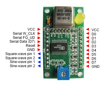
F4GOJ Christophe [email protected]
August 2014
AD9850 datasheet at http://www.analog.com/static/imported-files/data_sheets/AD9850.pdf
Use this library freely.
To use the AD9850 library:
- Go to https://github.com/F4GOJ/AD9850, click the Download ZIP button and save the ZIP file to a convenient location on your PC.
- Uncompress the downloaded file. This will result in a folder containing all the files for the library, that has a name that includes the branch name, usually AD9850-master.
- Rename the folder to AD9850.
- Copy the renamed folder to the Arduino sketchbook\libraries folder.
The AD9850 library instantiates a DDS object, the user does not need to do this.
#include <AD9850.h> //http://github.com/F4GOJ/AD9850
- W_CLK -> any pin
- FQ_UD -> any pin
- DATA/D7 -> any pin
- RESET -> any pin
Initialize the output pins and master reset the AD9850
DDS.begin(w_clk, fq_ud, data, reset);
w_clk : Working clock output pin, any pin (int)
fq_ud : Frequency update pin, any pin. (int)
data : Serial data output pin, any pin (int)
reset : Reset output pin, any pin. (int)
None.
void setup(){
 DDS.begin(6, 7, 8, 9);
}Compensation of crystal oscillator frequency.
Can be used at any time after initialization.
DDS.calibrate(trim_freq);
trim_freq : Adjust around 125000000 to match the real crystal oscillator frequency. (double)
None.
void setup(){
 DDS.begin(6, 7, 8, 9);
}

void loop(){
 DDS.calibrate(124999000);
}Sets the output frequency of the AD9850 and the phase of the signal.
DDS.setfreq(frequency, phase);
frequency : Output frequency in Hz. (double)
phase : Sets the phase of the output signal, coded on 5 bits allows 32 phase steps of 11,25° each. (int)
None.
double frequency = 10000000;
int phase = 0;
DDS.setfreq(frequency, phase);Power down mode reducing the dissipated power from 380mW to 30mW at 5V
DDS.down();
None.
None.
DDS.down();Wakes-up the AD9850 from power down mode.
DDS.up();
None.
None.
DDS.down(); // Entering power down mode

// some code doing something

...

DDS.up(); // WAKE-UP !!! :)