Enabling SPI mode for TMC2130 drivers in RAMPS requires lot of wiring. I wanted to have clean setup and created this simple board.
I used 10p flat cable to connect the board to RAMPS. Board itself has 10p IDC male header and the flat cable is split to 10p and 8p IDC female headers connected to RAMPS AUX-2 and AUX-3 (SPI) headers. AUX-3 header has 4 wires connected in the center (both sides 2 pins not connected).
The TMC2130 drivers are connected using wires directly soldered to the driver boards and 4p dupont connectors on the other end.
CS pins for X, Y, Z, E0 and E1 in RAMPS in my setup:
- X: 65
- Y: 42
- Z: 40
- E0: 64
- E1: 44 (not used)
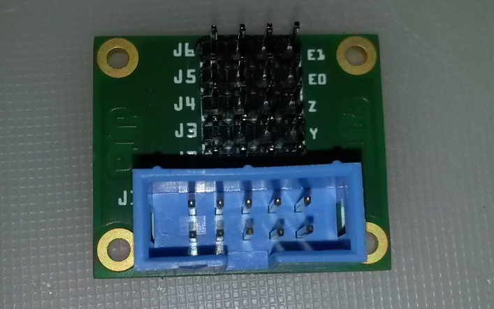
Driver pins in board from left to right (viewed above with 10p connector in bottom):
1: CS
2: SCK
3: SDO
4: SDI
PCBs were manufactured by Aisler and can be ordered here: https://aisler.net/p/MLBWSEVN
Complete board with all connectors:
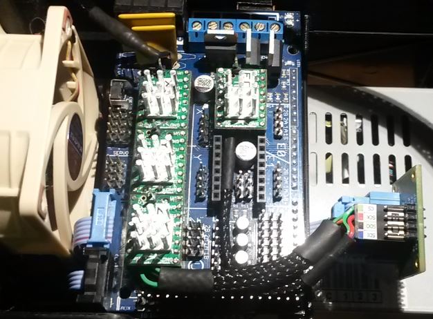
Board connected to RAMPS: