Wiring Everything Together
This page describes how to wire the components of the Electronic Leadscrew together. Since this is a DIY project, different people will choose to do it in different ways, using different cable and connector systems. This page describes the connections and gives some hints and suggestions.
This page assumes you are using an official Clough42 ELS Boost interface PC board. If you aren't you will need to provide level conversion, optocoupler driver, 3.3VDC power, EEPROM and other circuitry. You cannot connect any of the hardware (except the encoder) directly to the LaunchPad board. Connecting 5V logic directly to the LaunchPad pins will destroy it.
Before you begin, you will need to acquire the parts. For information on the parts you will need and where to acquire them, look here:
Before you begin, you will want to configure your new TI LaunchPad board. There are a few jumpers and switches that need to be changed from the defaults for the board to work with the Electronic Leadscrew. Specifically, you will need to:
- Move Switches S3 and S4 to the positions shown to enable the EQEP1 encoder input. You will need to peel the Kapton tape off the switches to access them.
- Move both S3 switches toward "QEP Select"
- Move S4 away from "35/37 Route"
- Remove the USB power jumpers (JP1/JP3/JP3) to isolate the USB port from the ELS power supplies
 (click to enlarge)
This diagram shows how all of the components are wired together. This is for illustration only. Choose appropriate cables and connectors for your installation. This diagram shows a three-phase hybrid servo. Your servo or stepper system may be different.
 (click to enlarge)
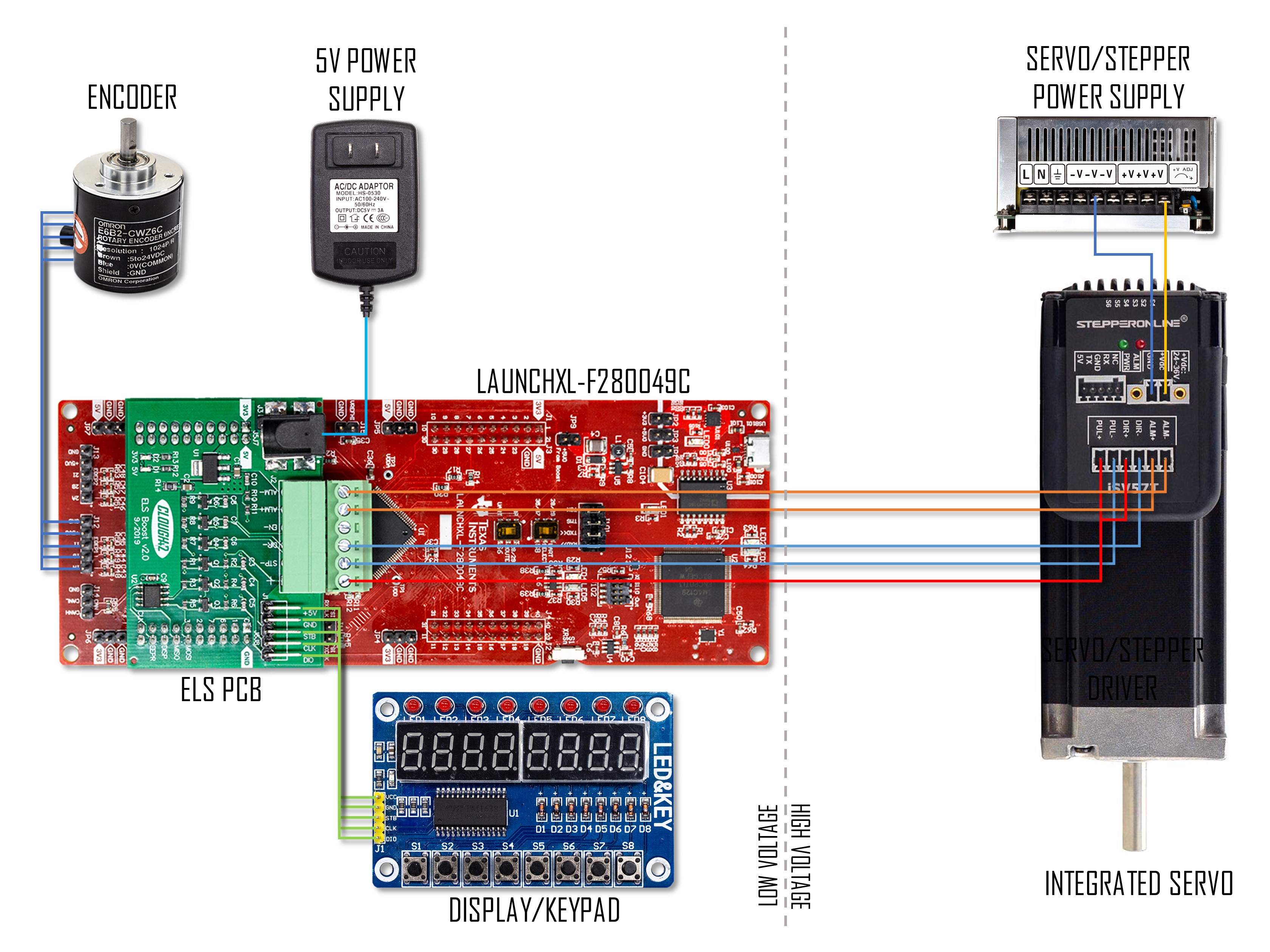 (click to enlarge)
- DO NOT CONNECT THE HIGH-VOLTAGE AND LOW-VOLTAGE GROUNDS. The driver has optically-isolated inputs so a common ground between the motor system and the electronics is not necessary. Having a common ground will cause issues with electrical interference and may cause safety concerns.
- Keep the display cable as short as possible. This display board uses a bidirectional, open-drain SPI protocol. Long cables have higher capacitance and can cause prevent proper communication. If the display is blank, behaves erratically, or the buttons do not work, check your wiring first, and then try a shorter cable.
- Keep the high-voltage and low-voltage parts of the system as far apart as practical. Don't run the encoder, display, or DC power wires in a bundle with the stepper or servo power wires. Shielded cable is a good idea, but keeping the cables apart will help more.
- If you use shielded cable, connect the shield to a chassis earth ground at one end only. Don't connect this to the logic ground or the motor power ground. Keep it separate and connect it at only one end.
- The encoder usually has five wires, plus a shield. Check the markings on the LaunchPad board to determine the correct pins for 5V power, ground, A, B and I (index) wires. Connect the shield to a chassis ground, if practical.
- Note that the Step/Direction/Enable lines to the stepper or servo driver are common-positive. The interface board provides only one + output. This needs to be connected to the positive terminals for all three inputs at the driver.
If you're having trouble, try checking the continuity of your connections.