-
Notifications
You must be signed in to change notification settings - Fork 44
LEDs (Optional)
Soldering the LEDs is a good first step as they are susceptible to heat damage. If you damage one, you may not want it attached to a PCB to which you've already attached several other components. If you decide to not install LEDs, you can add them later, but you will first need to desolder the nearby switches to have room to solder the LEDs.
The LEDs go on top, facing down, rotated to align with ground pad.
First ensure you have the proper tools. I found a normal solder tip more useful than a pointy SMT one.
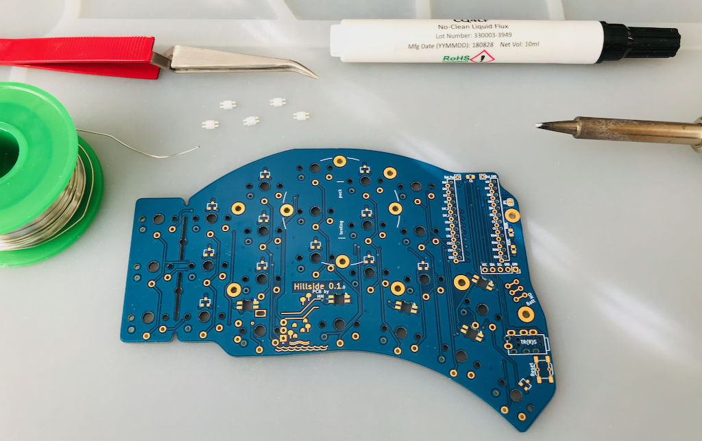
Add flux to the pads on the board to make this easier. Tin one pad of each LED footprint on the board. You will be less prone to make mistakes if you tin the same pad for each footprint, within each half of the board.
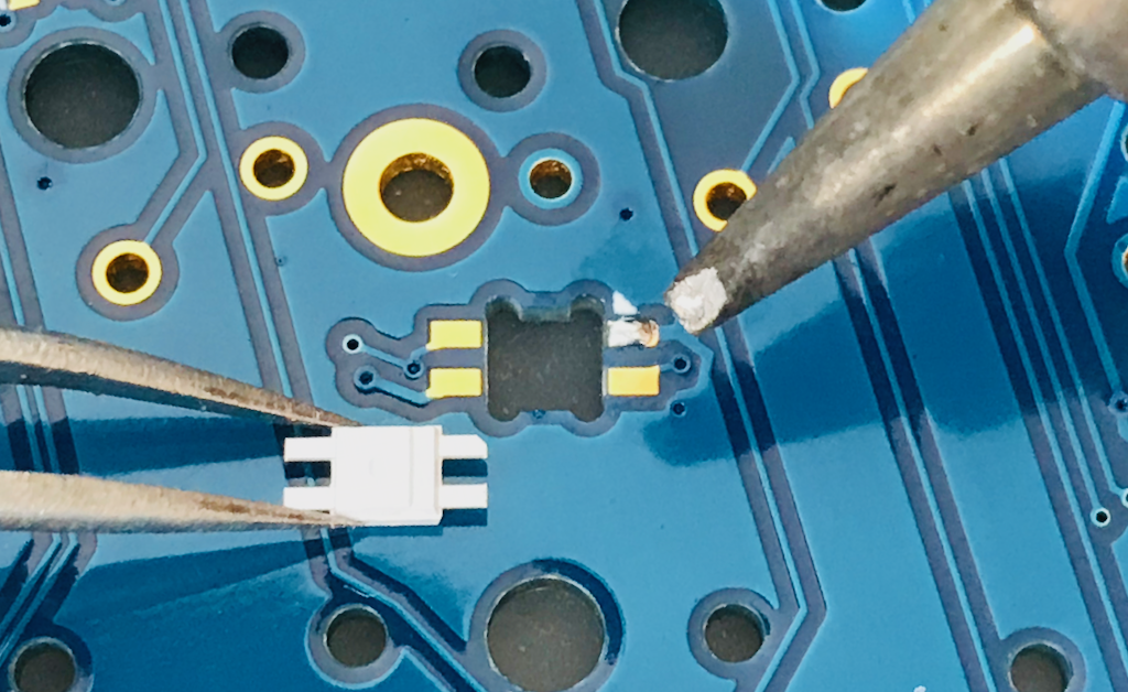
Grip LED with reverse tweezers, place it in the cutout with the notched leg aligned with the pad with the triangle next to it. These are the ground leg and pad.
With the iron in one hand and the tweezers holding the LED in the other, remelt the solder on the pad. As the solder melts, gently push the LED down so the leg is flat on the board. Ideally, some solder will flow on top of the leg as you do this. If the LED is rotated sideways, adjust it with the tweezers so it is fairly square and all the legs and pads have room to be soldered. Perfectly aligned is not necessary though.
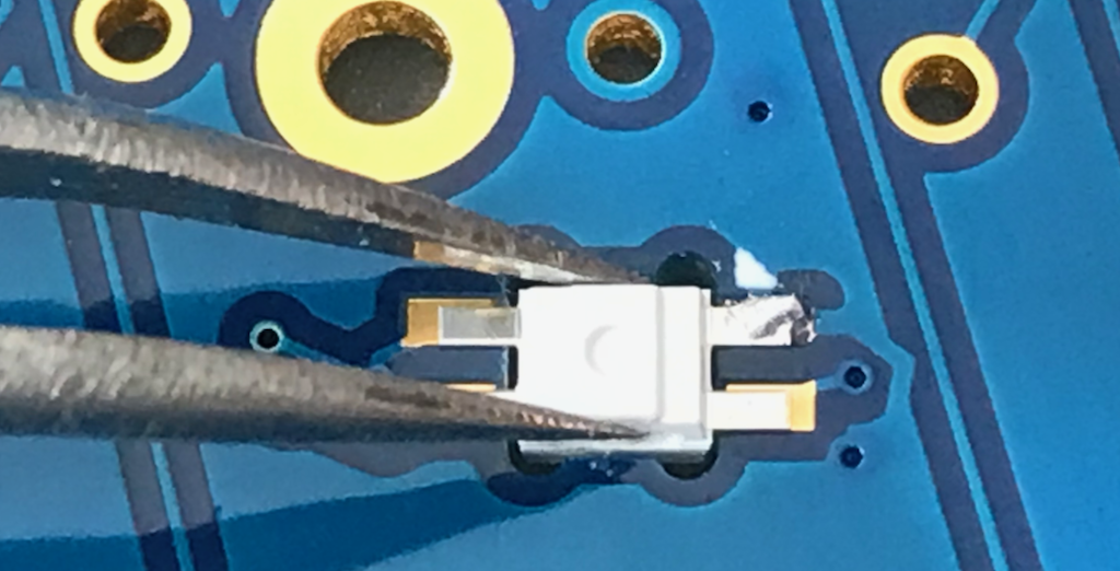
Repeat for the other LEDs to let this one cool.
Examine each LED to see that it is flat on the board, i.e. does not have legs sticking up in the air. Fix any as needed by remelting the one pad holding it in place.
Solder each LEDs remaining legs, and add solder to any of the original legs that need it. Be gentle with the solder you add. Less solder is better.
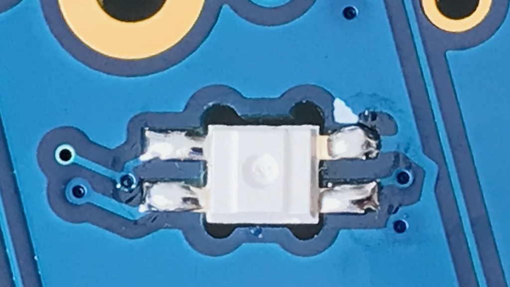
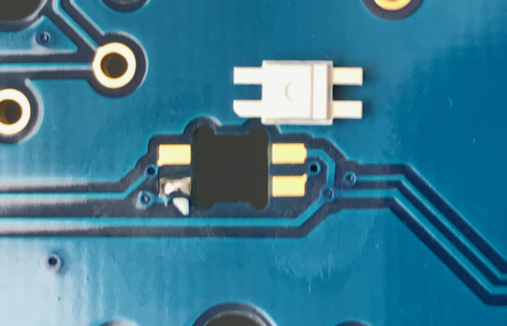
On other half of the keyboard, again align the leg with the cut out corner with the triangle icon on board. As the board is now flipped that orientation will be different that before.
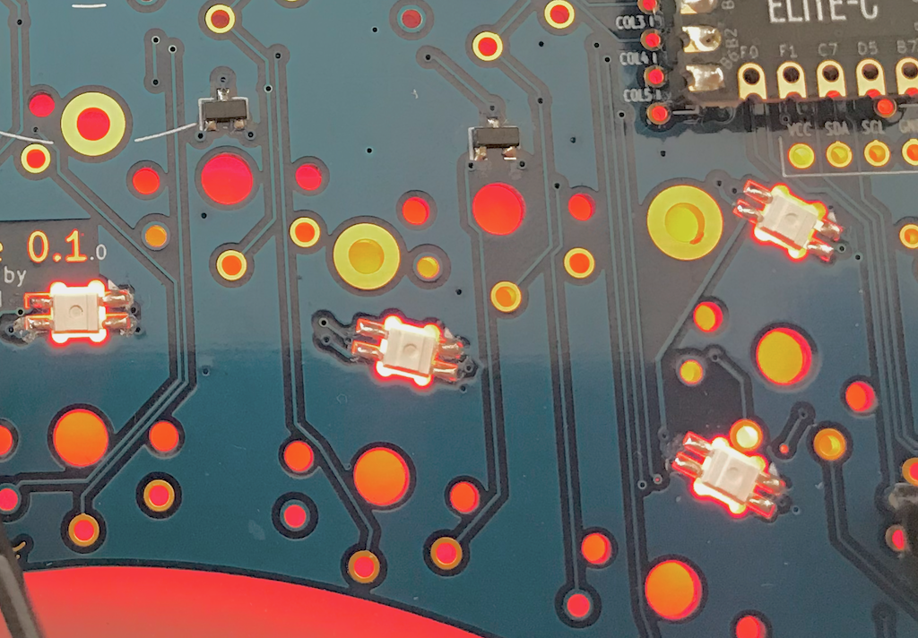
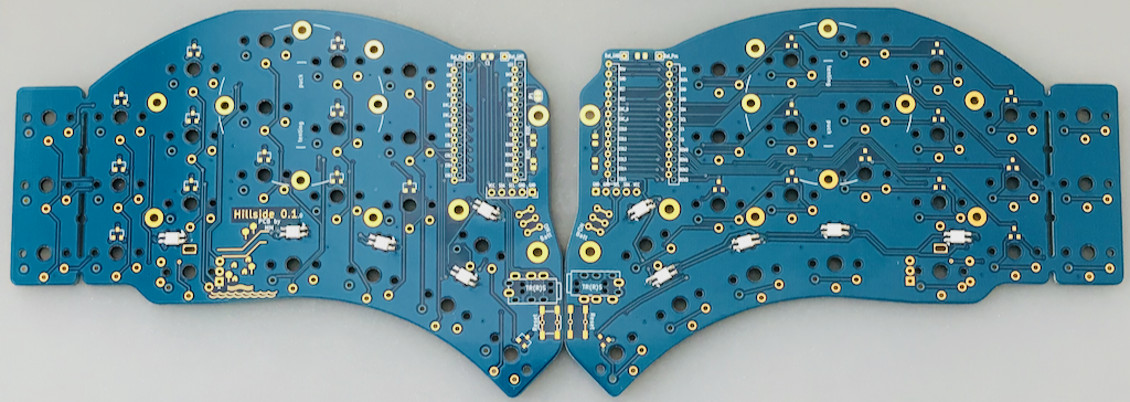
The finished board halves should look like this, with the LEDs on the top side of each half.
A little of the LED light leaks upward out of the cutout when lit. To help mitigate this, the LEDs are hidden by the keycaps. But if it is bothersome, some nail polish into the top of each cutout might hide it nicely, though I've not tried that yet.
Next: Resistors (Optional)