Push a button, do a POST (or GET) Request.
- POST/GET Requests
- Trigger Action
- Monitor Battery
- Power Saving
- Reconfigurable
Originally forked from Luigi-Pizzolito/IFTTT-Dash-Button (then de-forked since the scope of my project is different). More here. Power Latch idea originally by Rui Santos but I wanted to use an off-the-shelf component, namely the "Flip-Flop Latch Bistable Self-locking Trigger Switch" available on Aliexpress.
When the button is pushed a POST or GET request is made to a webpage.
Depending on the webpage, many different actions can be triggered by the button. I use mine to toggle a ESPHome/Tasmota switch.
When a request is made, if the setting is set, the button will also pass on the battery voltage with your web request. This way you can monitor the battery's charge. The server will recieve:
yoururl.com/yourrequest/?VCC_Param.=VCC_Voltage
To keep the button down to a small size, a small battery needs to be used. Pressing the button activates the latch and allows power. The ESP reboots, makes a POST/GET request and then activates the latch to cut power again.
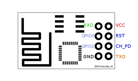
You dont need to take apart your button to re-program the url or action. If you connect GPIO_03[RX] to GND during startup the button will enter configuration mode. Then you can
- Connect to 'ESP_Button' WiFi Access Point, with the password 'wifibutton'
- Visit http://192.168.4.1 to open the configuration page
- After setting your values, click on the 'Save' button then the 'Restart'


- An off-the-shelf power latch:


- Similiar Projects
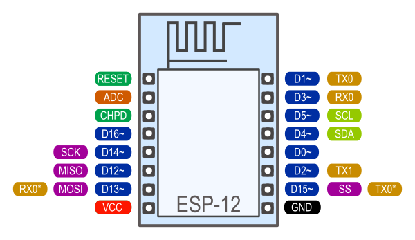
- ESP Info
- Pinouts
- General Guides
- GitHub Markdown Info
- I updated this github to show what actually worked but I never completed this project partly because I kept ruining batteries trying to squeeze everything into the tiny enclosure (including a charge circuit with a USB port). Also, I think this type of project could be done just as well using vanilla Tasmota.
- You can still use almost the same circuit as above but because you can just connect the D1 to a computer, there's no need for a config button. Once connected to a steady power source, the latch can't cut the power anyways.
- The 100K resistor in the diagram below is NOT needed. It just allows the latch to interrupt Tasmota from booting if you should change your mind and decide to shut off the D1. I think perhaps the ESP8266 is pulling the circuit high on boot, and the button then has no effect. Without the 100K, the latch circuit will still operate just fine but it's up to Tasmota to shut off the power.

The Template:
{"NAME":"DashButton","GPIO":[0,0,0,0,256,288,0,0,0,0,0,0,0,0],"FLAG":0,"BASE":18}
Needed console options:
Backlog SwitchMode1 2; WifiConfig 7; PowerOnState 0; SetOption36 0; SetOption65 1
Explanation:
SwitchMode1 2 - set switch to inverted follow mode
WifiConfig 7 - set Wi-Fi Manager (web server at 192.168.4.1) as the current configuration tool restricted to reset settings only
(4 may also work if you want to retry other AP without rebooting)
PowerOnState 0 - keeps power off (to the latch) after power up
SetOption36 0 - disable boot loop control
SetOption65 1 - disable device recovery using fast power cycle detection
Rule1 (contains boot commands, activates Rule2 and Rule3):
Rule1 ON Power1#Boot DO Backlog Rule2 On; Rule3 On; LedPower1 1; Var1 0; Delay 20; RuleTimer1 30 ENDON ON System#Boot DO Backlog LedPower1 0; Var1 1 ENDON
Rule2 (contains the WebQuery loop, activates Rule3 when ready to shutdown - change the WebQuery as needed):
Rule2 ON Var1#State==1 DO Backlog LedPower1 1; WebQuery http://192.168.1.82/cm?cmnd=Power%20Toggle POST ENDON ON WebQuery#Data=Done DO Backlog Var1 4 ENDON ON WebQuery#Data$!Done DO Backlog Var1 2 ENDON ON Var1#State==2 DO Backlog LedPower1 0; Delay 20; LedPower1 1; Var1 1 ENDON ON Rules#Timer=1 DO Backlog Var1 3 ENDON ON Var1#State==3 DO Backlog LedPower1 0; LedPower1 1; LedPower1 0; LedPower1 1; LedPower1 0; LedPower1 1; LedPower1 0; Var1 5 ENDON ON Var1#State==4 DO Backlog LedPower1 0; LedPower1 1; LedPower1 0; Var1 5 ENDON
Rule3 (deactivates Rule2 to prevent looping due to Webquery delays and does shutdown):
Rule3 ON Var1#State==5 DO Backlog Rule2 Off; Power1 0; Delay 5; Power1 1; Delay 5; Power1 0 ENDON
Var1 Values [and led actions]:
0 Boot [led on]
1 Wi-fi connected [led off], attempting action [led on]
2 Action Failed (delay 2s, try again) [off 2s]
3 Total Failure & shutdown [off; on; off; on; off; on; off (quick)]
4 Success [off; on; off (quick)]
5 Shutdown [led on until shutdown]
It's probably best to somehow use the port of the TP4056 to pass-through the data pins to the D1 mini's port or just use a board that has a battery charging circuit available.
This allows charging of the Battery via the D1 Mini port and still allow the D1 to be flashed via PC. Of course, the Dash button will come online and execute an action while being charged and the button would be completely useless to stop it unless you complicate the rules further to check for the voltage level... I use a 560K resistor despite seeing a 500K is recommended to check for 5V... I'm not very certain what the lowest value resistor you can use here but the A0 pin may be damaged if exposed to more than 1V so if your selection of resistors is limited err on the side of higher resistance...

The Template:
{"NAME":"DashButton","GPIO":[0,0,0,0,256,288,0,0,0,0,0,0,0,4704],"FLAG":0,"BASE":18}
Use the same console options as above:
Backlog SwitchMode1 2; WifiConfig 7; PowerOnState 0; SetOption36 0; SetOption65 1
Also need to set some ADC Parameters (with a 560K resistor measures >400 if charging and below 200 if on battery power):
AdcParam 6, 0, 1023, 0, 1000
Rule1 (combines Rule1 and Rule3 from above: contains boot commands, activates Rule3 with 5=ONCE, deactivates Rule2 to prevent looping due to Webquery delays and does shutdown):
Rule1 ON Power1#Boot DO Backlog Rule2 Off; Rule3 5; Rule3 On; LedPower1 1; Var1 0; Delay 20; RuleTimer1 30 ENDON ON System#Boot DO Backlog LedPower1 0; Var1 1 ENDON ON Var1#State==5 DO Backlog Rule2 Off; LedPower1 1; Power1 0; Delay 10; Power1 1; Delay 10; Power1 0 ENDON
Rule2 (same as above: contains the WebQuery loop, activates Rule1 when ready to shutdown - change the WebQuery as needed):
Rule2 ON Var1#State==1 DO Backlog LedPower1 1; WebQuery http://192.168.1.82/cm?cmnd=Power%20Toggle POST ENDON ON WebQuery#Data=Done DO Backlog Var1 4 ENDON ON WebQuery#Data$!Done DO Backlog Var1 2 ENDON ON Var1#State==2 DO Backlog LedPower1 0; Delay 20; LedPower1 1; Var1 1 ENDON ON Rules#Timer=1 DO Backlog Var1 3 ENDON ON Var1#State==3 DO Backlog LedPower1 0; LedPower1 1; LedPower1 0; LedPower1 1; LedPower1 0; LedPower1 1; LedPower1 0; Var1 5 ENDON ON Var1#State==4 DO Backlog LedPower1 0; LedPower1 1; LedPower1 0; Var1 5 ENDON
Rule3 (checks A0 pin for high voltage and sets Var1 to 6 if true, then deactivates Rule2 and Rule3):
Rule3 ON Analog#A0>300 DO Backlog Var1 6; Rule2 Off; Rule3 Off ENDON ON Analog#A0<=300 DO Backlog Rule2 On; Rule3 Off; Var1 1 ENDON
Var1 values are the same as above except that if high voltage (charging) is detected, it will be equal to 6 and the led will turn off (the TP4056 should have leds that indicate charging state).
Some other caveats of using this circuit is that sometimes while charging, the latch is actually on so when unplugging the device, the device remains on. You should be able to press the button to simply fully turn it off. Also, sometimes when pressing the button too soon after charging, the D1 will fail to boot. I'm not sure why that is.
You may need to check the A0 output in a web browser. The number 300 in Rule3 worked for me but it may not work for you, especially if you use a different resistor. The easiest way would be to plug it into a computer, see what the high end number is, click the button to activate the latch, wait until the RulesTimer expires (30s) then unplug it and wait a bit for A0 to level out, then choose a number about midway (preferably with a fully-charged battery).