Home
This getting started guide outlines how to:
- Create a new gateware project for the SmartFusion2 using Libero
- Create a new MSS design using Libero SystemBuilder
- (------TO BE ADDED------) Add custom gateware to the design
- Make the necessary top-level connections using Libero SmartDesign
- Add constraints to a file
- Running synthesis and place-and-route
- Program the SmartFusion2 FPGA
- Configure and export firmware for programming under Microsemi's SoftConsole
- Configure the software project and create debug configurations
- Run a debug configuration on the SmartFusion2 MSS
It is based upon DigiKey's Getting started guide, but covers the basic use of the M2S-MKR-KIT only, without the attached ESP peripherals. For using those peripherals, DigiKey's guide is more suitable.
- For first-time use using gateware and software design, the entire getting started guide should be read sequentially.
- For gateware-only design, only the gateware design section can be followed
- For software-only design, only the firmware design section can be followed
The schematics for the M2S010-MKR-KIT board can be downloaded from Digikey:
The various tools can be obtained from Microsemi's website:
Software and firmware files, for reference:
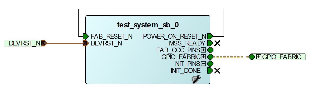
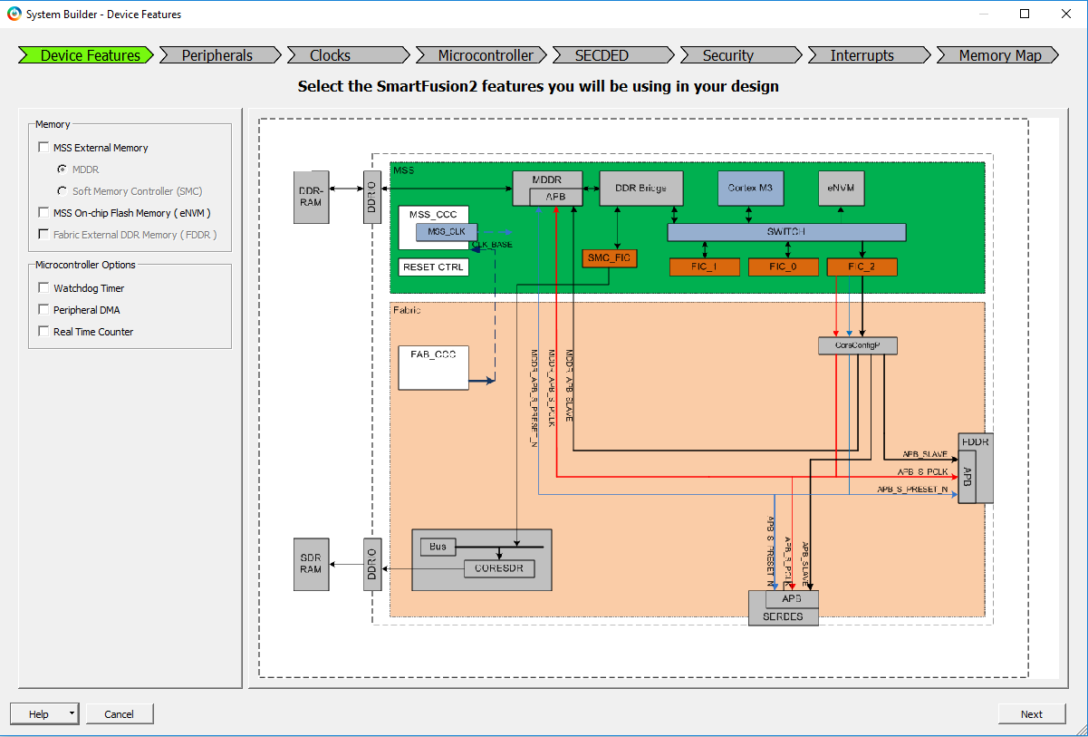
The simple MSS-based design shown below will be created. This design connects the MSS GPIO to the device pins via the logic fabric; the pins finally connect to LEDs on the M2S010-MKR-KIT.
Follow these steps to configure the design:
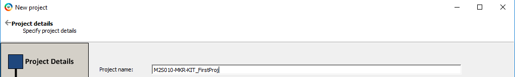
- Start Libero SoC and create a new project. Name it
M2S010-MKR-KIT_FirstProjand click Next.
- Select "M2S010-TQ144". Click Next.

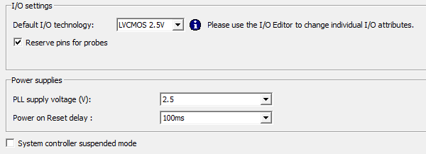
- Under Device Settings, click Next to accept the default settings.
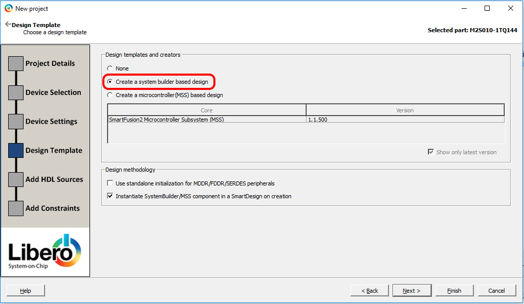
- Select Create a system builder based design and click Next.
-
No HDL sources or constraints will be added at this time. Click Finish.
-
If you are prompted to select a constraint flow, choose Enhanced Constraint Flow.
-
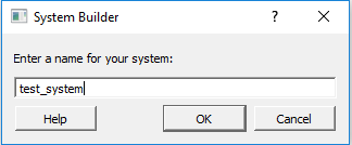
Libero will ask you to name the system. Give it the name
test_systemand click OK.
- The System Builder startup window will appear. Click Next to accept the defaults.
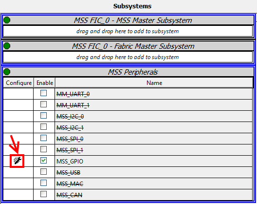
- In the Peripherals sub-window under System Builder, in the Subsystems pane, disable all peripherals. Enable MSS_GPIO and click the configuration button next to the Enable tick-box.
- Configure GPIO_0 through GPIO_7 as outputs connected to fabric, as shown below.

-
Click OK in the MSS GPIO Configurator window and click Next back in System Builder.
-
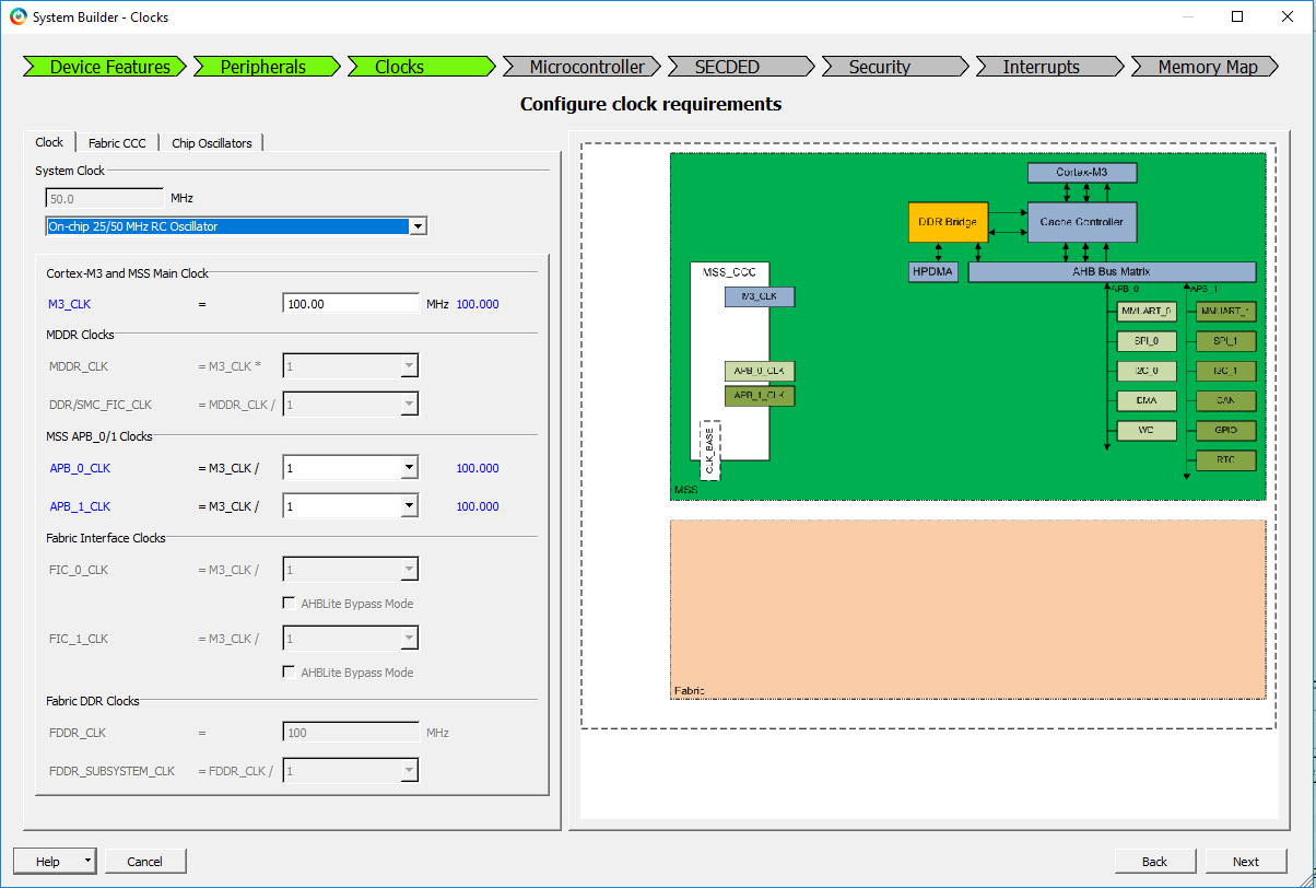
In the Clocks sub-window in System Builder, select On-chip 25/50 MHz RC Oscillator. Leave the rest of the settings to default (M3_CLK = 100 MHz) and click Next.
-
Click Next in the Microcontroller sub-window to accept the defaults.
-
Click Next in the SECDED sub-window to accept the defaults.
-
Click Next in the Security sub-window to accept the defaults.
-
Click Next in the Interrupts sub-window to accept the defaults.
-
Click Finish in the Memory Map window. The System Builder design should now be finished.
-
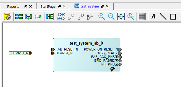
The generated MSS system should now appear in SmartDesign.
-
Select the GPIO_FABRIC interface, right-click and select Promote to Top Level in the pop-up menu. This will create an output port called GPIO_FABRIC and connect the MSS design to the port.
-
Expand the FAB_CCC_PINS and INIT_PINS interfaces.
-
Right-click MSS_READY and click Mark Unused in the pop-up-menu.
-
Right-click FAB_CCC_GL0 and click Mark Unused in the pop-up-menu.
-
Right-click FAB_CCC_LOCK and click Mark Unused in the pop-up-menu.
-
Right-click INIT_DONE and click Mark Unused in the pop-up-menu.
-
Make a connection between the POWER_ON_RESET_N and FAB_RESET_N pins of the MSS using the Connection mode button in SmartDesign (alternative: Right-click > Connection mode within the SmartDesign window).
-
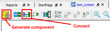
Save the design, then click the Generate component button in SmartDesign (alternative: Right-click > Generate component within the SmartDesign window).
-
In the Design Flow pane to the left of the Libero window, double-click Synthesize.
-
You will see a number of warnings in the messages that refer to unused components and can be safely ignored.
-
When synthesis has completed, double-click Manage Constraints in the Design Flow pane.
-
Choose New > Create New I/O Constraint from Root Module and give the constraint a name (the one in the example design was given the name
user) and click OK. Libero will auto-generate a constraint file populated with the top-level ports from the block diagram. -
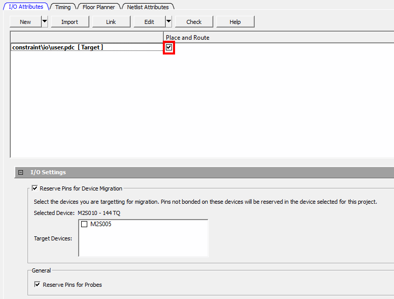
Back in the Constraint Manager window, right-click the new constraint and click Set as Target.
-
Tick the tick-box under Place and Route for the constraint.
-
Select Edit > Edit with I/O Editor.
-
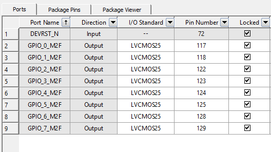
Make the following settings in the I/O Editor window:
-
Save the constaints and close the I/O Editor.
-
Back in the Design Flow pane, double-click Place and Route.
-
When Place and Route has completed, run Generate FPGA Array Data.
-
After the FPGA array data is generated, run Generate Bitstream.
-
Near the bottom of the Design Flow pane, select Configure Firmware Cores.
-
Make sure all the available firmware is selected for generation. There should be one for each peripheral enabled at the beginning. Libero will ask to download any cores that are not already present on the computer.
-
From the Design Flow pane, choose Export Firmware. Choose a location for the export and set the Software IDE to SoftConsole 4.0. This automatically selects the Export hardware configuration and firmware drivers setting.
-
Connect the M2S010-MKR-KIT to your computer using a USB cable.
-
Choose Run PROGRAM Action from the Design Flow pane to load the configuration onto the board.
-
Make sure the report appearing in the Reports window returns a success.
Follow these steps:
-
In the Design Flow pane, double-click Export Bitstream under Handoff Design for Production.
-
The Export Bitstream window will appear. Select a location where the file should be exported to and make sure STAPL and Fabric are ticked. You may optionally add a suffix for the name by typing in some text in the text box.

-
Click OK. After a while, the bitstream is exported into a STAPL (.stp) file to the location of your choice. This STAPL file can be used by anyone to program the bitstream using FlashPro.
-
Make sure the report appearing in the Reports window returns a success.
Using the MSS system generated in the steps above, we can now proceed to writing some firmware to light the LEDs. We will use the firmware generated from Libero in the steps above along with some custom code to blink the LEDs on the M2S010-MKR-KIT.
In case you are only developing firmware for the SmartFusion2 MSS and have not yet downloaded the binary to the FPGA (done in Step 38 above), you can use the STAPL file exported from Libero and FlashPro to do this.
-
Save the contents of the STAPL programming file at this location to a new file called test_system.stp. In Firefox, for example, this is a simple Right click > Save Page As... command. In other browsers, you may need to copy and paste the file's contents into a new file.
-
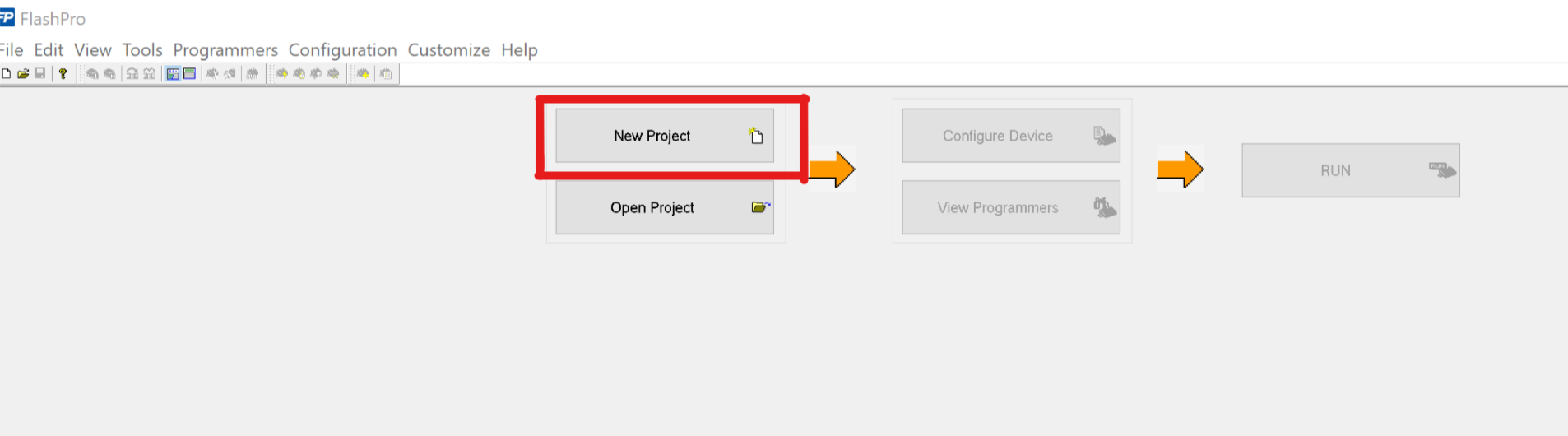
Start FlashPro and click on New project when UI has loaded (or Open project if you already have an existing project).
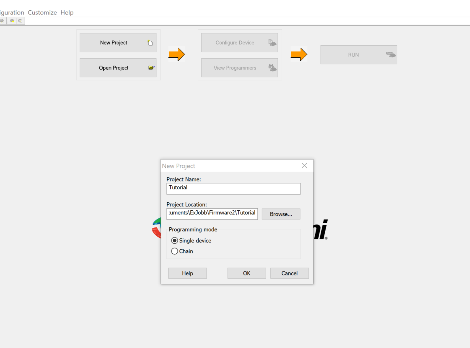
- Select your project name and location.
- Click on Configure device.

- Click on the Browse button next to load existing programming file and browse to the location of your test_system.stp file.

-
Make sure that the mode is in Basic, and the action is Program. If the board was programmed earlier, you can verify the version with Verify.
-
Click on Program and make sure that the output screen at the bottom of the FlashPro window does not contain any errors.
Follow these steps:
-
Open SoftConsole and choose a convenient directory as the workspace.
-
In SoftConsole, select File > New > Project...
-
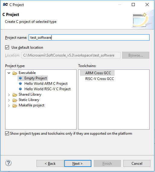
In the window that opens, select C Project and click Next.

- Name your software
test_softwareand choose a location for the project. Click Next to create an Empty project using ARM Cross-GCC toolchain.
-
Click Next to add the default Debug and Release configurations to the project.
-
Click Next to accept the default Toolchain settings.
-
Your new project is created. Right-click it in the Project Explorer pane and click Import...

- In the Import window that opens, select File System and click Next.

- Browse to the
firmware/directory under the gateware project directory, select it and click OK. (If you are only working with firmware design, you can grab thefirmware/directory from the Libero .zip archive.)

- Click the firmware folder tick-box in the Import window, click the Create top-level folder tick-box and click Finish.

-
Your test_software project is now ready for writing some code to blink the LEDs. Time to create a C file to contain our
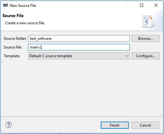
main()function. Run File > New > Source file. -
In the window that appears, give the file the name
main.cand make sure it lies under the "test_software" folder. Click Finish.
- The new source file should open. If it doesn't, open it by double-clicking it in the Project Explorer pane. Copy the following code to the file (identical to that in the main.c source file from the repository):
#include "firmware/drivers/mss_gpio/mss_gpio.h"
#include "firmware/CMSIS/system_m2sxxx.h"

static const mss_gpio_id_t LED[8] = {
		MSS_GPIO_0, MSS_GPIO_1, MSS_GPIO_2, MSS_GPIO_3,
		MSS_GPIO_4, MSS_GPIO_5, MSS_GPIO_6, MSS_GPIO_7,
};

void delay()
{
	int d = SystemCoreClock / 128;

	while (d-- > 0)
		;
}

int main(void)
{
	int i, current_val;

	MSS_GPIO_init();

	/* Init & turn on all LEDs */
	for (i = 0; i < 8; i++) {
		MSS_GPIO_config(LED[i], MSS_GPIO_OUTPUT_MODE);
		MSS_GPIO_set_output(LED[i], 0);
	}
	delay();
	delay();
	delay();
	delay();

	/* Blink all LEDs on start up */
	for (i = 0; i < 8; i++) {
		for (current_val = 0; current_val < 8; ++current_val)
			MSS_GPIO_set_output(LED[current_val], 1);
		delay();
		for (current_val = 0; current_val < 8; ++current_val)
			MSS_GPIO_set_output(LED[current_val], 0);
		delay();
	}

	/* Sequence-blink */
	for (;;) {
		for (i = 0; i < 8; i++) {
			current_val = (MSS_GPIO_get_outputs() & (1 << LED[i])) ? 1 : 0;
			MSS_GPIO_set_output(LED[i], current_val ^ 1);
			delay();
		}
	}
}
-
Right-click the project in the Project Explorer pane and click Properties.
-
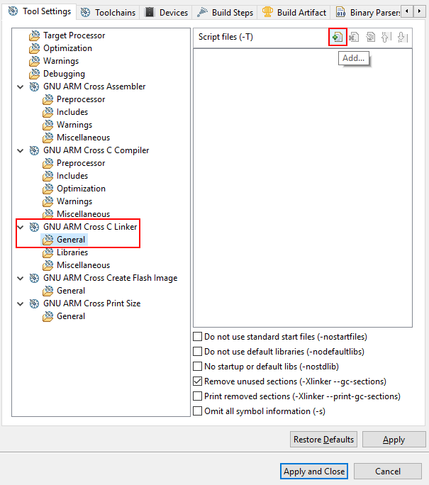
In the Properties window that opens up, navigate to C/C++ Build > Settings.
-
In the Tool Settings tab, navigate to GNU ARM Cross C Linker > General and click the Add button under Script files (-T):
- In the window that opens up, add the relative path to the linker script:
../firmware/CMSIS/startup_gcc/debug-in-microsemi-smartfusion2-esram.ld
-
Under GNU ARM Cross C Linker > Miscellaneous, tick the Use newlib-nano (--specs=nano.specs) tick-box.
-
Under GNU ARM Cross C Compiler > Miscellaneous, fill in the following in the Other compiler flags field:
--specs=cmsis.specs
-
In the Toolchains tab, tick Create extended listing.
-
Click Apply and Close.
-
Build the project by hitting Ctrl+B on your keyboard, or clicking the build button. The project should build successfully.

-
In the file menu, click Run > Debug Configurations....
-
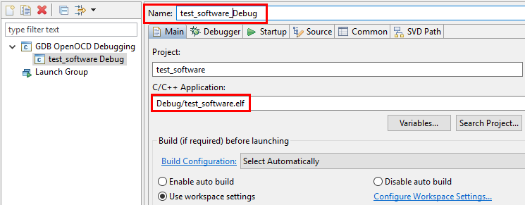
Double-click GDB OpenOCD Debugging. In the Main tab, name the new configuration
test_software_Debugand replace the backslash with a forward slash in the C/C++ Application text box (this is to make the project portable on Linux).
- In the Debugger tab, add the following text under Config options:
--command "set DEVICE M2S010" --file board/microsemi-cortex-m3.cfg
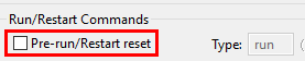
- In the Startup tab, scroll down to the Run/Restart Commands section and disable the Pre-run/Restart reset tick-box.
-
Plug the M2S010-MKR-KIT into a USB port and click Debug.
-
The Debug window should appear and a breakpoint is set on entry to the
main()function. Click the Run button to run the program.

-
The LEDs should now be blinking. At first all LEDs will blink simultaneously, then they will be turned on and off sequentially.
-
Play around in the code to see changes taking effect. For example, change the division factor in the
delay()function, build and debug the project again. Note that the build step is necessary prior to debugging.
In order to have the firmware running on startup, it must be programmed into the eNVM (embedded non-volatile memory) of the SmartFusion2 FPGA. This is done by simply changing the linker script in step 17 above to the eNVM linker script,
debug-in-microsemi-smartfusion2-envm.ld
The full process to do this follows:
-
Right-click the project in the Project Explorer pane and click Properties.
-
In the Properties window that opens up, navigate to C/C++ Build > Settings.
-
In the Tool Settings tab, navigate to GNU ARM Cross C Linker > General and click the Add button under Script files (-T).
-
In the window that opens up, add the relative path to the linker script:
../firmware/CMSIS/startup_gcc/debug-in-microsemi-smartfusion2-envm.ld
The next time debug runs, code will be downloaded to the eNVM and will start executing upon subsequent power-ups.
NB: The linker script shown here is a demonstration for the example project. For your own project, a release build should be compiled and downloaded to the eNVM.
![]()