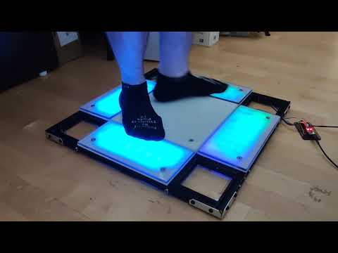
Hi, I'm Widget, and these are the files for my ITG dance/travel pad.
This is the "v0" version, currently in prototype status. I don't plan on deviating too far from these plans, but there are more adjustments I still want to make to make the pad easier to manufacture, easier to fork the source code for, and have it perform more consistently.
You can find me on the Stamina Nation discord causing problems in #pads.
If you live in Chicago and can pass stamina 16's or higher, I would be interested in having you try out the prototype in person for feedback. Let me know on Discord.
Current pads either suck or are >$1000. LTEKs are acceptable but need significant modding using custom microcontrollers and the fragile "penny mod", so why not just make a new pad?
Currently it's mainly competing with Bandit's Build This Travel Pad and Bandit's Terrific Travel Pad budget designs.
- Aluminum extrusion frame (2020 profile)
- 1/2" acrylic panels
- Arduino Pro Micro microcontroller (but with plans to switch to Teensy 4.0)
- Force-sensitive resistors for configurable sensitivity
- Allows for rather extreme sensitivity if made with good tolerances
- Optional LED grid PCBs (WS2812C LEDs)
GNU GPL v2. See LICENSE for full text.
- Arduino Pro Micro or Teensy 2.0 or higher
- 4x 220 ohm resistors
- Some wire to extend FSR connections
- Panels, cut or precut:
- Either
- 4x 12mm thickness 280mm x 280mm acrylic panels (1/2" thickness 11"x11") or larger
- Or
- 1x 280mm x 280mm precut acrylic center panel
- 4x 280mm x 125mm precut acrylic side panels
- 4x 125mm x 125mm precut acrylic corner panels (optional)
- Optionally, acetal (a.k.a. POM, Delrin) as a slipperier center panel instead of acrylic
- Either
- Aluminum extrusion (2020 profile)
- All taps should be M6 taps with 10mm depth
- Extra depth is acceptable but may require longer M6 threaded rods
- 2x 544mm extrusions
- Drill 6mm at holes at 10mm, 129.5mm, 414.5mm, and 534mm
- Countersink these holes for your 6mm bolts as well
- 4x 504mm extrusions, both ends tapped
- Drill 6mm holes at 109.5mm and 394.5mm
- For 2 extrusions, countersink these holes for your 6mm bolts as well
- For the other 2 extrusions, extra holes for wiring recommended
- 2x 265mm extrusions, both ends tapped
- Extra holes through the center for wiring recommended
- 4x 99.5mm extrusions, both ends tapped
- Extra holes through the center for wiring recommended
- All taps should be M6 taps with 10mm depth
- Force sensitive resistors (4x 200mm Interlink 408 or 8x Interlink 400)
- 12x countersunk M6x30mm bolts
- 12x hex-head M6x30mm bolts
- 4x M6x40mm threaded rods
- 16x M6 threaded inserts for plastic
- 40x M5x10 bolts
- 40x M5 hammer nuts for 2020 aluminum extrusion
- An "engineering" filament for 3D printed parts, such as PETG, nylon, or polycarbonate
- Optional: cross brackets and angle brackets for stability
- Optional: rubber bumpers for floor safety and/or better pad sensitivity
- Optional: 128 WS2812C-5050 LEDs for PCBs
- Optional: 8x 1x2 2.54mm-pitch right-angle male PCB headers for PCBs
- Optional: 4x 5.04mm-pitch 1x2 screw terminals for PCBs
- Optional: 8x 5.04mm-pitch 1x3 screw terminals for PCBs
- Table saw if acrylic cutting needed
- Drill press with 6mm (1/4") drill bit and 45° countersink bit
- Table router and roundover bit or lots of sandpaper for smooth edges
- 3mm and 4mm allen keys
- 3D printer for panel mounts
- A heated tool of some sort, such as a soldering iron or a lighter and a rod of some type, for inserting the threaded inserts
- Soldering iron is required if assembling PCBs
- DuPont wire crimpers may be useful for making "extension cords" for the FSR connectors
3D printed parts can be found in the 3d/ folder.
Parts are designed using OpenSCAD with the BOSL2 library. OpenSCAD nightlies and BOSL2 master branch are recommended.
Corner bracket mounts will need to be 3D printed to connect the panels to the aluminum frame.

Strong filaments, at a minimum PETG but preferably nylon or polycarbonate will be required. Brittle filaments like PLA, ABS, HIPS, and ASA may crack. High-rigidity TPU filaments (Shore hardness 98A or higher) may work, but soft filaments may cause the panels to slide during play.
A soldering iron or other heating tool will be needed to melt the threaded inserts into the 3D printed part for the panels to connect to.
PCB mounts may also be 3D printed.
A housing will eventually be designed for the microcontroller but not as part of v0.
The microcontroller breakout is for a Teensy 4.0 or Teensy 4.1.
The Teensy 4.0 will allow control of up to 10 FSRs, which can map to up to 10 panels, or 2 FSRs on up to 5 panels.
The Teensy 4.1 will allow control of up to 18 FSRs, which allows an amount of flexibility with regards to a high-end setup:
- 4 FSRs on each of 4 panels (dance)
- 2 FSRs on each of 8 or 9 panels (techno)
- 2 or 3 FSRs on 4 panels and 4 on a center panel (pump)
- 4 FSRs on 4 panels, and 2 on a center panel (pump)
The breakout also has:
- A 3-pin JST-HX connection for panel LEDs
- 9 LEDs for checking FSR pressed status
- 4 external buttons, for an external arcade button assembly
- 3 internal buttons for controlling LED brightness, and triggering an as-yet-unwritten pad calibration
- A buzzer or speaker, to add audio "tactility" to pressing the panels
- A jumper to bridge USB power with the external power input for LEDs
The breakout is designed using KiCAD and uses teensy_library and teensy.pretty by XenGi, released under the BSD license.
The PCBs are designed using KiCAD.

The PCBs each hold an 8x4 grid of WS2812C LEDs. An external 5V power source is recommended if using LEDs.
Each PCB has screw terminals for connecting the WS2812C inputs and outputs. In addition, there are 3 positions of screw terminals and headers for connecting one or more FSRs. Multiple FSRs would be wired in parallel.
- Cut all aluminum extrusion pieces to length, if not precut
- Cut drills and countersinks in extrusion
- Tap all extrusion pieces 10mm deep except the two longest ones, if not pretapped
- Use threaded rods to attach small extrusions "through" the two longer center ones
- Bolt the four second-longest extrusions to the longest two extrusions
- Insert threaded inserts (using heat) into 3D printed panel mounts
- Attach 3D printed panel mounts to corners of frame using M5 hammer nuts
- Optionally add cross braces and corner brackets, and add rubber feet to the bottom of the frame
- Cut all panels to correct size
- Preferably using a drill press, cut holes 30mm inset from each corner
- Four holes on the center panel
- Two adjacent holes on the edge panels
- Two opposing holes on the corner panels
- Use a countersink bit to countersink the holes
- Using a table router with a roundover bit or lots of sandpaper, smooth the edges so that your socks don't get torn up
This pad uses typical wiring for FSR-based pads. Each FSR should connect to an analog pin an the microcontroller with a 220 ohm pulldown resistor with the other side connected to VCC.
LED boards will need a connection to VCC, GND, and a data pin, typically D10 on the Arduino Pro Micro.
An external 5V power source is recommended if using LEDs.
One or more large capacitors (47μF or larger) across +5V and GND may help with signal stability if the LEDs are causing noise in the FSR signals.


See also this diagram by Bandit.
The dimensions are currently calculated using Fusion 360, but I hate Fusion 360 so eventually I'll change it over to OpenSCAD as well.

The firmware is still a work in progress and can be found at widget-/bttp-firmware. It is a fork of Bandit's BTTP pad's firmware.
Currently it supports joystick or keyboard input, and allows an arbitrary amount of buttons with corresponding optional LED strips. Sensitivity can be adjusted either in the firmware or with a tool such as the bttp-config-tool.
- Bandit, for motivating me to make this pad, as well as giving me one of his prototype pads to play on.
- dominick and teejusb for their help and experience
- The rest of #pads for keeping me motivated
- South Side Hackerspace, for having all the equipment used to create the prototype