3. "Hello World" Tutorial
This tutorial is actually a bit more than "just" the classical "Hello World". It contains six small sub-tutorials to get you started:
- Classical "Hello World" using the Welcome-Screen
- Add a new menu-item and show an "About & Help" menu
- Add two menu-items: Flip the joystick ports and mute the siren
- Use multi-select menu items to change the color of the "ball"
- Filter files: Only show
*.txtfiles in the file browser - Understanding the QNICE debug console
[@lydon: Here we could advertize your YouTube video]
Please make sure that you have completed the First Steps before
proceeding with the tutorials shown here. Use the MyFirstM2M clone you made
there for the following exercises.
By default, the Welcome-Screen is shown after power-on (and/or loading the
core, respectively) and after each reset. You can configure this behavior in
the file CORE/vhdl/config.vhd:
-- show the welcome screen in general
constant WELCOME_ACTIVE    : boolean := true;

-- shall the welcome screen also be shown after the core is reset?
-- (only relevant if WELCOME_ACTIVE is true)
constant WELCOME_AT_RESET  : boolean := true;
For now, do not change anything here, yet, because we want to use the Welcome-Screen to show our "Hello World" message.
Search for the constant SCR_WELCOME in config.vhd. You will notice that
this is quite a long, multi-line string constant. You will recognize the
contents of the Welcome-Screen that the demo-core is showing. Please be
aware that you can and need to use \n to add newlines so that you can format
your welcome screen.
Go to the lines that contains this segment:
   "\n\nEdit config.vhd to modify welcome screen.\n\n" &
   "You can for example show the keyboard map.\n" &
   "Look at this example from Game Boy Color:\n\n\n" &
Replace the segment with your personal "Hello World!" message for example:
"\n\nHello World! Hello M2M! Hello MEGA65!\n\n\n\n" &Generate a bitstream and run the core.
After that, you might want to set the above-mentioned flags to false so that
the Welcome-Screen disappears completely: It will neither be shown upon the
initial startup of the core then nor will it be shown after a reset.
This mini-tutorial catches two birds with one stone:
- You'll get a first sense for how the on-screen-menu works
- You'll understand the help-system
M2M contains a help-system that allows you to have up to 15 help topics, where each help topic can have 256 screens. Let's add a menu item that shows some demo help content.
Search for the constant OPTM_SIZE in config.vhd and change its value
from 25 to 27.
Add this to the string constant OPTM_ITEMS before the "Close Menu" item:
" About & Help\n"        &
"\n"                     &
The string constant should now look like this:
constant OPTM_ITEMS        : string :=

   " Demo Headline A\n"     &
   "\n"                     &
   " Item A.1\n"            &
   " Item A.2\n"            &
   " Item A.3\n"            &
   " Item A.4\n"            &
   "\n"                     &
   " HDMI Frequency\n"      &
   "\n"                     &
   " 50 Hz\n"               &
   " 60 Hz\n"               &
   "\n"                     &
   " Drives\n"              &
   "\n"                     &
   " Drive X:%s\n"          &
   " Drive Y:%s\n"          &
   " Drive Z:%s\n"          &
   "\n"                     &
   " Another Headline\n"    &
   "\n"                     &
   " HDMI: CRT emulation\n" &
   " HDMI: Zoom-in\n"       &
   " Audio improvements\n"  &
   "\n"                     &
   " About & Help\n"        &
   "\n"                     &
   " Close Menu\n";
Now go to this block of constants:
constant OPTM_G_Demo_A     : integer := 1;
constant OPTM_G_HDMI       : integer := 2;
constant OPTM_G_Drive_X    : integer := 3;
constant OPTM_G_Drive_Y    : integer := 4;
constant OPTM_G_Drive_Z    : integer := 5;
constant OPTM_G_CRT        : integer := 6;
constant OPTM_G_Zoom       : integer := 7;
constant OPTM_G_Audio      : integer := 8;
And add one more:
constant OPTM_G_AboutHelp : integer := 9;After that, locate the constant OPTM_GROUPS and add two more line items
right before this block:
     OPTM_G_LINE,                              -- Line
     OPTM_G_CLOSE                              -- Close Menu
   );
The line items that you should add are these:
     OPTM_G_LINE,                              -- Line that separates the Help menu
     OPTM_G_AboutHelp + OPTM_G_HELP,           -- Show help topic #1
As a result, OPTM_GROUPS will look like this:
constant OPTM_GROUPS       : OPTM_GTYPE := ( OPTM_G_TEXT + OPTM_G_HEADLINE,            -- Headline "Demo Headline"
                                             OPTM_G_LINE,                              -- Line
                                             OPTM_G_Demo_A + OPTM_G_START,             -- Item A.1, cursor start position
                                             OPTM_G_Demo_A + OPTM_G_STDSEL,            -- Item A.2, selected by default
                                             OPTM_G_Demo_A,                            -- Item A.3
                                             OPTM_G_Demo_A,                            -- Item A.4
                                             OPTM_G_LINE,                              -- Line
                                             OPTM_G_TEXT,                              -- Headline "HDMI Frequency"
                                             OPTM_G_LINE,                              -- Line
                                             OPTM_G_HDMI + OPTM_G_STDSEL,              -- 50 Hz, selected by default
                                             OPTM_G_HDMI,                              -- 60 Hz
                                             OPTM_G_LINE,                              -- Line
                                             OPTM_G_TEXT,                              -- Headline "Drives"
                                             OPTM_G_LINE,                              -- Line
                                             OPTM_G_Drive_X + OPTM_G_MOUNT_DRV,        -- Drive X
                                             OPTM_G_Drive_Y + OPTM_G_MOUNT_DRV,        -- Drive Y
                                             OPTM_G_Drive_Z + OPTM_G_MOUNT_DRV,        -- Drive Z
                                             OPTM_G_LINE,                              -- Line
                                             OPTM_G_TEXT,                              -- Headline "Another Headline"
                                             OPTM_G_LINE,                              -- Line
                                             OPTM_G_CRT     + OPTM_G_SINGLESEL,        -- On/Off toggle ("Single Select")
                                             OPTM_G_Zoom    + OPTM_G_SINGLESEL,        -- On/Off toggle ("Single Select")
                                             OPTM_G_Audio   + OPTM_G_SINGLESEL,        -- On/Off toggle ("Single Select")
                                             OPTM_G_LINE,                              -- Line that separates the Help menu
                                             OPTM_G_AboutHelp + OPTM_G_HELP,           -- Show help topic #1
                                             OPTM_G_LINE,                              -- Line
                                             OPTM_G_CLOSE                              -- Close Menu
                                           );
Please note that the items in OPTM_GROUPS are having a 1-to-1 relationship
to each line (separated by \n) in OPTM_ITEMS. Also please note that
OPTM_ITEMS now has 27 lines and OPTM_GROUPS has 27 array elements,
just as specified by OPTM_SIZE.
That's it! You now have an "About & Help" menu item that opens demo content that is three screens long.
Try it: Generate a bitstream and play with it. You can open the "About & Help" menu using Return and you can browse through the multiple help pages using Cursor Left and Cursor Right. Press Space to close the help menu.
You will find a more in-depth description of how the Shell's menu system works here @TODO and all details about the help-system here @TODO. Nevertheless, here is the condensed overview:
-
OPTM_ITEMSdefines the names of the menu items andOPTM_GROUPSdefines the properties and behaviour of the menu items. There is a 1-to-1 relationship between both: A line inOPTM_ITEMScorresponds to an array element inOPTM_GROUPS. - Empty lines in
OPTM_ITEMSwill be shown as lines, when the corresponding entry inOPTM_GROUPSis set toOPTM_G_LINE. - Each menu item that is supposed to "do something" needs to be part of a
"Menu Group". This is why you defined the constant
OPTM_G_AboutHelpwhile following the recipe above. - Multi-select menu items need all to be in the same Menu Group. See how all
the "Item A.*" menu items are part of
OPTM_G_Demo_A. - Single-select menu items - such as the help menu item - need to have a
unique identifier ("Group"). This is why you gave your constant
OPTM_G_AboutHelpthe unique value9. - Attributes and properties can be added to Menu Groups using the
+operator because the values are arranged in a way that the Shell can recognize single bits. This is why you added theOPTM_G_HELPattribute to theOPTM_G_AboutHelpmenu item identifier. - The help system counts: The first menu item that has a
OPTM_G_HELPattribute will show the first help topic. The second menu item that has aOPTM_G_HELPattribute will show the second help topic, and so on. The various help menu items do not need to be in proximity. - The example
config.vhdfile provided with M2M contains a three-page (three-screen) demo help topic. This tutorial does not explain more details how the help-system itself works, but you can look at the constantsWHS_DATAandWHSto get a first overview or go to the reference page @TODO to learn more.
Now we are ready to add two menu items that change the actual state of the core: The first one will flip the joystick ports. The demo core's "BreakOut paddle" can not only be controlled by the cursor keys Left and Right but they can be also controlled by a joystick that sits in port #1. If you did not try this, yet, please do right now. After that, connect your joystick to port #2 and see how it is not working. We will fix that with our new menu-item.
The second menu item that we will add will be used to toggle the siren. By default it will be on so that the siren will be on. The flip joystick ports menu item will be off by default; so we will also learn how to work with default values.
If you followed the mini tutorial above, then you already know the trick
of how to add menu items to OPTM_ITEMS and OPTM_GROUPS. Let's get started:
Here are two new constants for our list of Menu Group constants:
constant OPTM_G_FlipJoys   : integer := 10;
constant OPTM_G_Siren      : integer := 11;
You can highlight headlines or sections in the menu using the
OPTM_G_HEADLINE attribute. Let's do that and create a completely new
section at the very top of the menu directly after the first stand-alone
"\n" (after " Demo Headline A\n"). Make sure that the first 10 lines of
OPTM_ITEMS look like this:
constant OPTM_ITEMS        : string :=

   " Demo Headline A\n"     &
   "\n"                     &
   " My Switches\n"         &
   "\n"                     &
   " Flip Joysticks\n"      &
   " Siren\n"               &
   "\n"                     &
   " Item A.1\n"            &
   " Item A.2\n"            &
   " Item A.3\n"            &
What we did: We added a headline called "My Switches" that is embedded between two new-lines ("empty lines"). We will make sure that these empty lines will be displayed as lines. We will also make sure that the headline "My Switches" will be displayed differently than the rest of the menu.
Before we proceed, let's count how many lines we added: We added five new
lines, starting with "My Switches" and ending with "\n". So let's update
OPTM_SIZE:
constant OPTM_SIZE : natural := 32; -- amount of items including empty lines:Last-but-not least, we need to define the semantics. Make sure that the first
10 lines of OPTM_GROUPS look like this (and make sure that you remove the
+ OPTM_G_HEADLINE after the very first OPTM_G_TEXT just as shown here):
constant OPTM_GROUPS       : OPTM_GTYPE := ( OPTM_G_TEXT,                              -- "Demo Headline" (standard look)
                                             OPTM_G_LINE,                              -- Line
                                             OPTM_G_TEXT + OPTM_G_HEADLINE,            -- Headline "My Switches": Yellow
                                             OPTM_G_LINE,                              -- Line
                                             OPTM_G_FlipJoys + OPTM_G_SINGLESEL,       -- Single select item: Flip joysticks; not selected by default
                                             OPTM_G_Siren + OPTM_G_SINGLESEL + OPTM_G_STDSEL, -- Single select item: Siren; selected by default
                                             OPTM_G_LINE,                              -- Line
                                             OPTM_G_Demo_A + OPTM_G_START,             -- Item A.1, cursor start position
                                             OPTM_G_Demo_A + OPTM_G_STDSEL,            -- Item A.2, selected by default
                                             OPTM_G_Demo_A,                            -- Item A.3
A single-select menu item is being created by using OPTM_G_SINGLESEL, and
adding OPTM_G_STDSEL makes sure that a menu item is on by
default.
Synthesize the core, run it and check - using the Help key - that the
menu is showing the expected menu items. Please note, that the headline
"Demo Headline" is no longer shown in yellow (as we removed
+ OPTM_G_HEADLINE) while "My Switches" is indeed shown in yellow. As soon as
this is successful, please continue with the next steps.
The user's menu choices are available in real-time in mega65.vhd via the
register qnice_osm_control_i, which is an input port to mega65.vhd:
-- On-Screen-Menu selections
qnice_osm_control_i     : in std_logic_vector(255 downto 0);
The prefix qnice_ means, that this signal / register is in the
"Clock Domain" of the QNICE System-on-a-Chip. At this moment you neither
need to understand what a "Clock Domain"
(or what Clock Domain Crossing (CDC)) actually is, nor do you need to
fully understand how QNICE works. The only important thing for now to know
right now is:
- Always connect signals of the same clock domain with each other.
- Do not connect signals of different clock domains with each other.
In our very example this means: It is no problem to wire qnice_osm_control_i
to the flip-joystick-port signal called qnice_flip_joyports_o. But it
would be a problem, if you propagated qnice_osm_control_i into for example
main.vhd that runs in the core's clock domain, and used it there. (Actually
it is not difficult to do that, if you work out the
Clock Domain Crossing (CDC), but for now, just ignore this and continue
with the tutorial's track.)
Go back to the file config.vhd and count (starting from zero) where the
two menu items we added are located. You need to count each line of
OPTM_ITEMS including text-only items and empty lines. After that, create
two constants in mega65.vhd that contain the position. Don't forget to
adjust the positions of the other, already existing demo-core menu items: They
changed when you added your new menu items. When you are done, the
section -- Democore menu items in mega65.vhd should look like this:
-- Democore menu items
constant C_MENU_FLIPJOYS      : natural := 4;
constant C_MENU_SIREN         : natural := 5;
constant C_MENU_HDMI_60HZ     : natural := 15;
constant C_MENU_CRT_EMULATION : natural := 25;
constant C_MENU_HDMI_ZOOM     : natural := 26;
constant C_MENU_IMPROVE_AUDIO : natural := 27;
Now let's make sure that M2M is informed about the user's intention to flip
the joystick ports; then M2M will do the rest for you. The
qnice_osm_control_i contains this information at position C_MENU_FLIPJOYS
so all we need to do is is to change this code here
-- Flip joystick ports (i.e. the joystick in port 2 is used as joystick 1 and vice versa)
qnice_flip_joyports_o      <= '0';
into this code here:
-- Flip joystick ports (i.e. the joystick in port 2 is used as joystick 1 and vice versa)
qnice_flip_joyports_o      <= qnice_osm_control_i(C_MENU_FLIPJOYS);
Next, let's make sure that the siren can be muted. Find the line that assigns
a zero to qnice_audio_mute_o and change it to this code:
qnice_audio_mute_o <= not qnice_osm_control_i(C_MENU_SIREN);We are using not because the semantics is: If the Siren menu item is on
then the siren should be audible.
Done. Pretty elegant, isn't it? Make a bitstream, run it and test it:
-
The siren is on. Press Space and play a bit. Your joystick should be in port #2, so you can move the paddle using the cursor keys but not using the joystick.
-
Open the menu by pressing Help and unselect "Siren": The siren should be immediatelly muted.
-
Choose "Flip Joysticks" and note, how the menu item is visually selected in the menu. If you move your joystick now, it will not yet work. The reason is: The menu is still open and
JOY_1_AT_OSDinconfig.vhdis set tofalsewhich means: While the menu is open, the joystick is disconnected from the core. -
Close the menu by pressing Help. Move your joystick to the left and to the right and note how the joystick moves the paddle.
The standard color of the ball is orange. Open main.vhd and search for
this line of code inside the instatiation of the entity work.democore:
ball_col_rgb_i => x"EE4020", -- ball color (RGB): orange What you are seeing here is, that the democore actually allows you to specify
the color of the ball in the RGB color format. RGB stands for red, green
and blue. If you enter rgb to hex in Google, then Google will present you
a small converter app. Copy the value shown above, i.e. EE4020 into the
"HEX" field of Google's app and you will immediately see the shade of orange
that is the default color of the ball.
You can now play around with the app's controls to find colors you like and then copy the hexadecimal value. For the sake of simplicity, we are just using red, green and blue, plus the original orange.
In main.vhd, between the keywords architecture and begin, add these
constants that either use your own colors - in this case you might want to
rename them - or just proceed with organge, red, green and blue:
-- Color constants for the ball
constant BALLCOL_ORANGE    : std_logic_vector(23 downto 0) := x"EE4020";
constant BALLCOL_RED       : std_logic_vector(23 downto 0) := x"FF0000";
constant BALLCOL_GREEN     : std_logic_vector(23 downto 0) := x"00FF00";
constant BALLCOL_BLUE      : std_logic_vector(23 downto 0) := x"0000FF";
The next step is something that you will very likely do more often than not
when porting MiSTer cores: You will add some signals to the interface of the
entity main. In some cases this might be due to additional clocks that
the core needs. In other cases you might need to add RAM or ROM signals where
these entities are managed inside mega65.vhd due to Clock Domain Crossing
topics. There might be control signals that you want to share. And so on. The
bottom-line is, that it is pretty normal and part of M2M's architecture that
you as a user of the framework add signals so that entity main can
communicate with entity MEGA65_Core (in mega65.vhd) and vice versa.
Remember: entity main is meant to be the place where the "MiSTer core can
peacefully live in its own little bubble and clocking domain and whatnot
without ever knowing anything about the MEGA65". This quote is from the First
Steps chapter of this Wiki; you might want to review the section
main.vhd: i_main.
In this step of our tutorial, our goal is to let the user choose the color
of the ball using the on-screen-menu. So our entity main needs to become
aware of what the user selected. One way of doing this is to provide
entity main with the vector that contains the on-screen-menu (OSM)
selections. Let's do that by adding these two lines after the pause_i
input port:
-- On-screen-menu selection
osm_i                   : in  std_logic_vector(255 downto 0);
The first 12 lines of entity main's definition should now look like this:
entity main is
   generic (
      G_VDNUM                 : natural                     -- amount of virtual drives
   );
   port (
      clk_main_i              : in  std_logic;
      reset_soft_i            : in  std_logic;
      reset_hard_i            : in  std_logic;
      pause_i                 : in  std_logic;

      -- On-screen-menu selection
      osm_i                   : in  std_logic_vector(255 downto 0);
Now we need to ensure that the entity MEGA65_Core (in mega65.vhd) is
actually sharing the OSM information with entity main. If you are using the
Vivado IDE, then you will already see a visual indicator of an error when
opening mega65.vhd and scrolling down to the module instatiation
i_main : entity work.main:
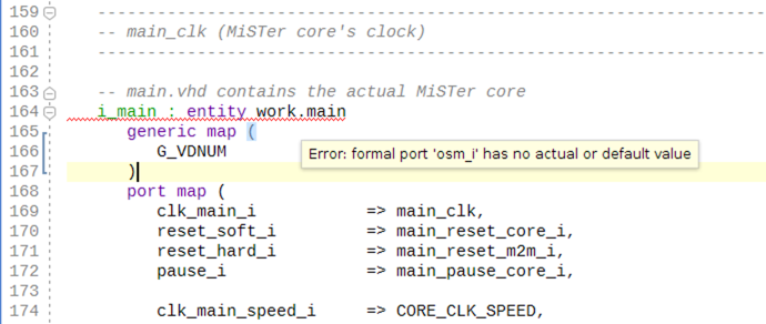
In other words: Vivado rightfully complains that we are not providing a value
for a mandatory input. We can correct this by passing the OSM status vector
to osm_i. As already explained above: Always connect signals of the same
clock domain with each other. Since the demo core (and all MiSTer cores) are
running in the main clock domain, we must not use the OSM vector
qnice_osm_control_i that we used above. The qnice_osm_control_i vector is
consisting of Flip-flops that are updated by the QNICE clock. Instead, we need
to use main_osm_control_i.
Add the following two lines of code in mega65.vhd after the pause_i port
mapping:
-- On-screen-menu selection
osm_i                => main_osm_control_i,
The first 12 lines of the instatiation of work.main should now look like
this:
i_main : entity work.main
  generic map (
     G_VDNUM              => C_VDNUM
  )
  port map (
     clk_main_i           => main_clk,
     reset_soft_i         => main_reset_core_i,
     reset_hard_i         => main_reset_m2m_i,
     pause_i              => main_pause_core_i,

     -- On-screen-menu selection
     osm_i                => main_osm_control_i,
We now need some menu items that the user of our demo core can select to
change the ball's color. So let's open config.vhd and re-use the
multi-select menu that is already there: Change the menu items "Item A.1" to
"Item A.4" into "Orange", "Red", "Green" and "Blue". The first
13 lines of the definition of OPTM_ITEMS should now look like this:
constant OPTM_ITEMS        : string :=

   " Demo Headline A\n"     &
   "\n"                     &
   " My Switches\n"         &
   "\n"                     &
   " Flip Joysticks\n"      &
   " Siren\n"               &
   "\n"                     &
   " Orange\n"              &
   " Red\n"                 &
   " Green\n"               &
   " Blue\n"                &
As you already learned above, the semantics - i.e. the meaning - of the
menu items are defined in OPTM_GROUPS. Let's review the entries of
OPTM_GROUPS that are associated to "Orange", "Red", "Green" and "Blue":
OPTM_G_Demo_A + OPTM_G_START,             -- Item A.1, cursor start position
OPTM_G_Demo_A + OPTM_G_STDSEL,            -- Item A.2, selected by default
OPTM_G_Demo_A,                            -- Item A.3
OPTM_G_Demo_A,                            -- Item A.4
We can see, that the "menu group" that represents our color selection is
called OPTM_G_Demo_A. If the framework encounters a group of menu items that
share the same "menu group" and if there is no other attribute that changes
the semantics, then the framework automatically generates a multi-select
menu section, in our case "Orange", "Red", "Green" and "Blue". The name of
the constant that we use to denote that menu group, in our case it is
OPTM_G_Demo_A does not matter. But it is a best practice to use meaningful
names, so let's change this into OPTM_G_BallCol. Go to the definition of
our menu group constants and change the first one like this so that the
first three lines of the menu group constant definition now look like this:
constant OPTM_G_BallCol    : integer := 1;
constant OPTM_G_HDMI       : integer := 2;
constant OPTM_G_Drive_X    : integer := 3;
Next, change the OPTM_GROUPS string and the comments like this:
OPTM_G_BallCol + OPTM_G_START,            -- Organge, menu's cursor start position
OPTM_G_BallCol + OPTM_G_STDSEL,           -- Red, selected by default
OPTM_G_BallCol,                           -- Green
OPTM_G_BallCol,                           -- Blue
The meaning of the OPTM_G_START start flag is: This is the menu item, where
the selection cursor should be placed when opening the menu by pressing
the Help key. In our example this means: The selection cursor will
be placed over "Orange". But orange will not be the default color that the
ball will have when you start the core. Instead, "Red" will be the default
because the flag OPTM_G_STDSEL is added to the position where "Red" is
located.
As a final step, we need to add some logic that translates menu selections
into a color input for the demo core. Open main.vhd and add constants that
represent the positions of the menu items for "Red", "Green" and "Blue". We
will not need the position for "Orange" because we will utilize the orange
color as our internal default value (independent from the settings above). You
might recall: You need to count the position of the menu line item starting
from zero in OPTM_ITEMS in config.vhd. Doing so yields the following
positions, given that you followed the whole tutorial from the beginning:
-- Position constants for osm_i
constant C_MENU_RED        : natural := 8;
constant C_MENU_GREEN      : natural := 9;
constant C_MENU_BLUE       : natural := 10;
Make sure that you are adding this constant definitions in main.vhd (not
in mega65.vhd). A good place to put them is right below the color constants.
Next, we need a signal that represents the selected color. Add the following
two lines below the position constants that you just added in main.vhd:
-- Signal that contains currently used color constant
signal   ball_color        : std_logic_vector(23 downto 0);
Now we change the hardcoded color value EE4020 to the dynamically evaluated
color value ball_color by changing the input of the demo cores's port
ball_col_rgb_i that you have seen at the very beginning of this section
like this:
ball_col_rgb_i => ball_color, -- ball color chosen via OSM What is still missing is the actual logic that translates the OSM selection
into a color value. Add the following process below the begin keyword that
follows the architecture keyword but before the instantiation of the
demo core i_democore : entity work.democore:
select_ball_color : process(osm_i)
begin
  ball_color <= BALLCOL_ORANGE;    -- default value; make sure that no latch is synthesized

  if osm_i(C_MENU_RED) then
     ball_color <= BALLCOL_RED;
  elsif osm_i(C_MENU_GREEN) then
     ball_color <= BALLCOL_GREEN;
  elsif osm_i(C_MENU_BLUE) then
     ball_color <= BALLCOL_BLUE;
  end if;
end process;
Most of this code is straightforward: We have a purely combinatorial process. If a certain bit is set in the OSM vector then assign the approriate color constant to the color signal. A question might arise around the first assignment:
ball_color <= BALLCOL_ORANGE; -- default value; make sure that no latch is synthesizedThe reason why we are using such a default value (which could also have been
wrapped inside a final else clause) is: osm_i has many more states than
just the few states we are interested in here. If we would not specify any
else or default value in the process then a latch would be synthesized
to hold the value of ball_color steady in all the cases that are not
"mentioned" in the process. This is not, what we want. Instead, what we want
here is that ball_color is a pure combinatorial signal. And this is also
why we did not need any position constant for "Orange" because "Orange" is
the default case of the process.
Now it is time to synthesize and run the core. You will notice that:
- Below the "Siren" menu item and the line there are four menu items called "Orange", "Red", "Green" and "Blue".
- The menu selection cursor when you press Help is located over
"Orange", that means if you wanted to use the "Flip Joysticks" menu item,
you would need to press Cursor Up two times. Reason: We have
chosen "Orange" as the menu item, that is selected by default when opening
the menu for the first time using the flag
OPTM_G_START. - The color of the ball is red from the start. Reason: We have chosen
red as the default color using the flag
OPTM_G_STDSEL. - You are able to switch the ball's color in real-time by choosing the different menu item and then pressing Return. This is expected because most things inside an FPGA happen in parallel to each other. The demo core is not aware that a QNICE core is running which shows any menu. The demo core is just aware of the input port that specifies the ball color.
@TODO @TODO @TODO
@TODO @TODO @TODO
@TODO @TODO @TODO
@TODO @TODO @TODO