Section 3.1 Assembly of the XZ Unit Mounting the X Axis
|
|
|
|
|
|
|
|
|
|
|
-
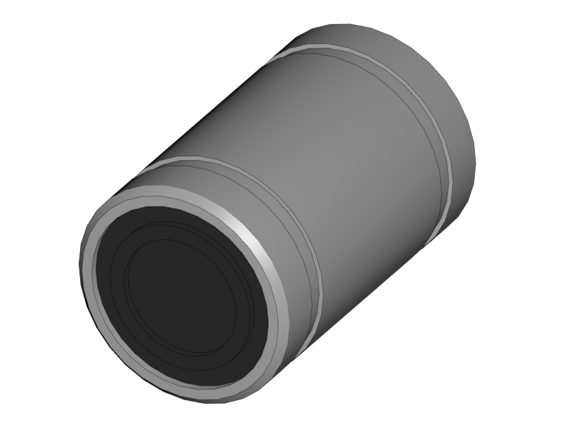
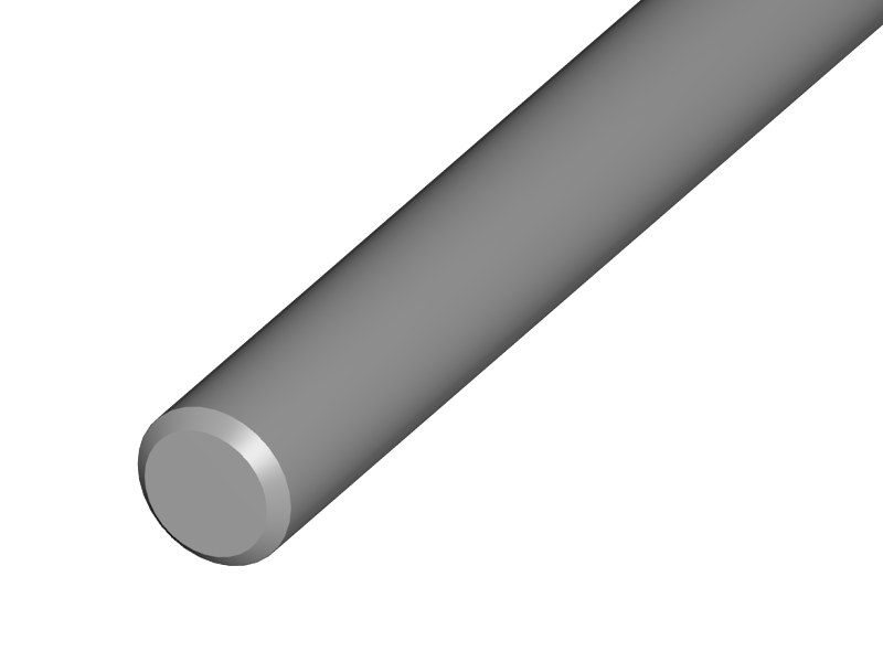
Put the linear bearings onto any of the smooth rods
-
This is to keep the bearings straight while you mount them.
-
-
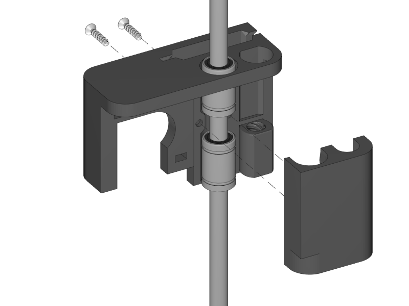
Put the bearings and the rod into the bearing slots of the X-Motor
-
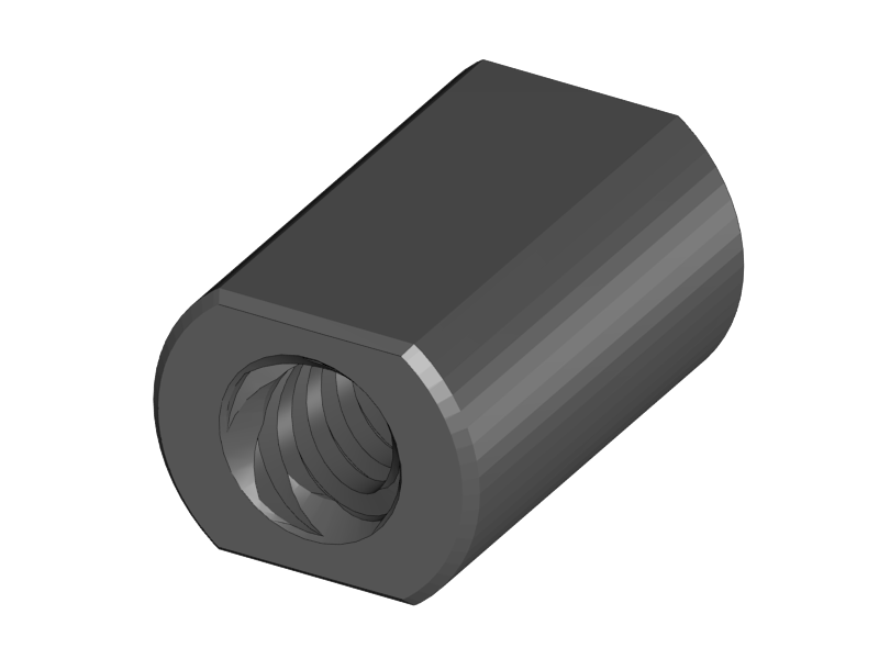
Put the ACME Nut into the slot of the X-Motor Holder
-
You can find the ACME Nut on the threaded rod of your linear stepper motor
-
-
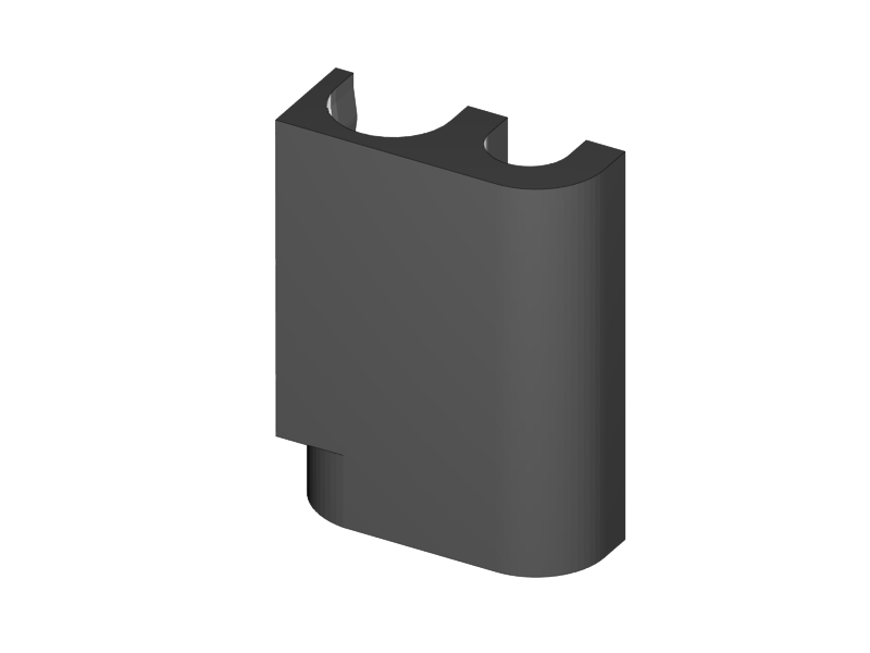
Place the Bearing Holder
-
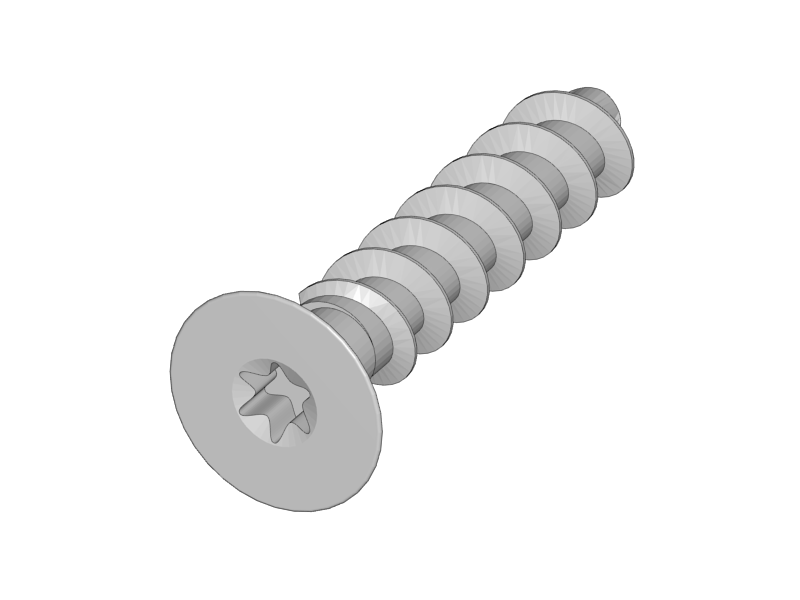
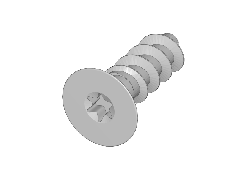
Fix the Bearing Holder with the two Torx screws.
-
Remove the smooth rod
|
|
|
|
|
|
|
-
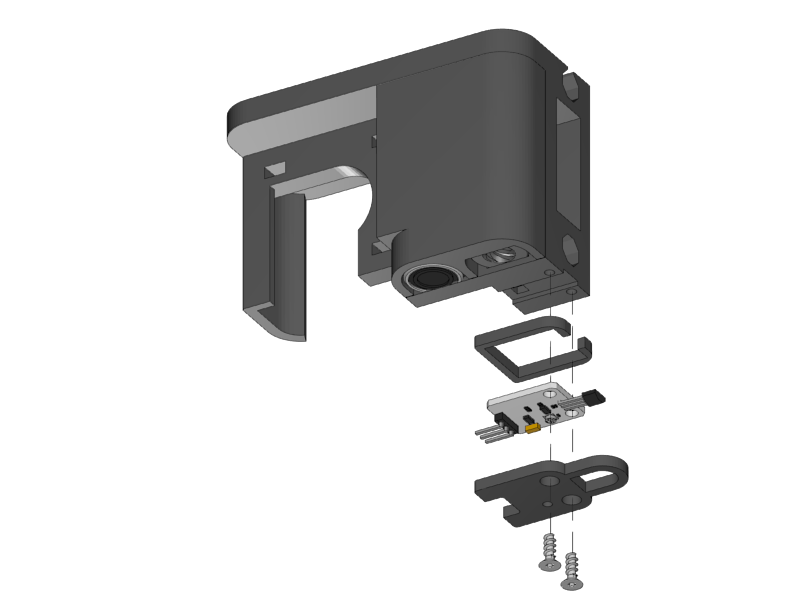
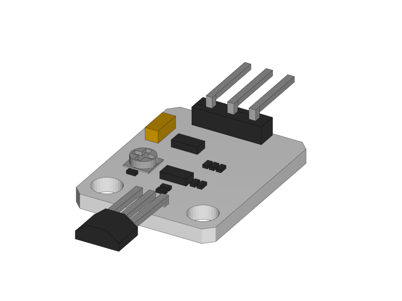
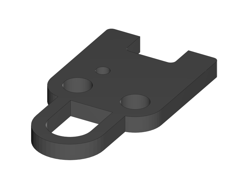
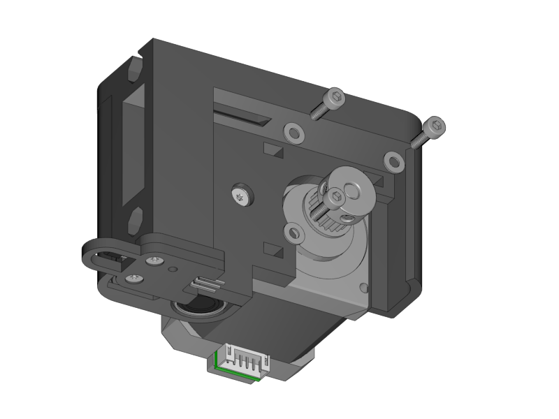
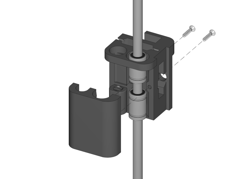
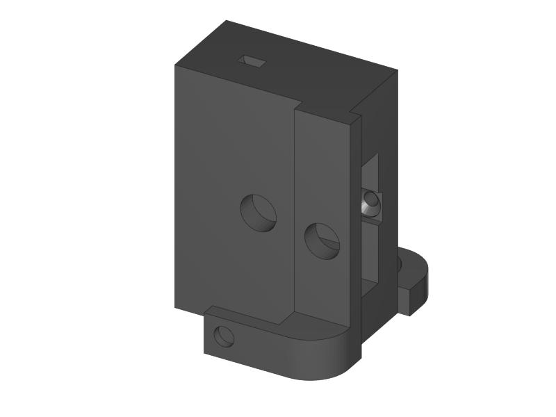
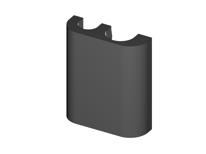
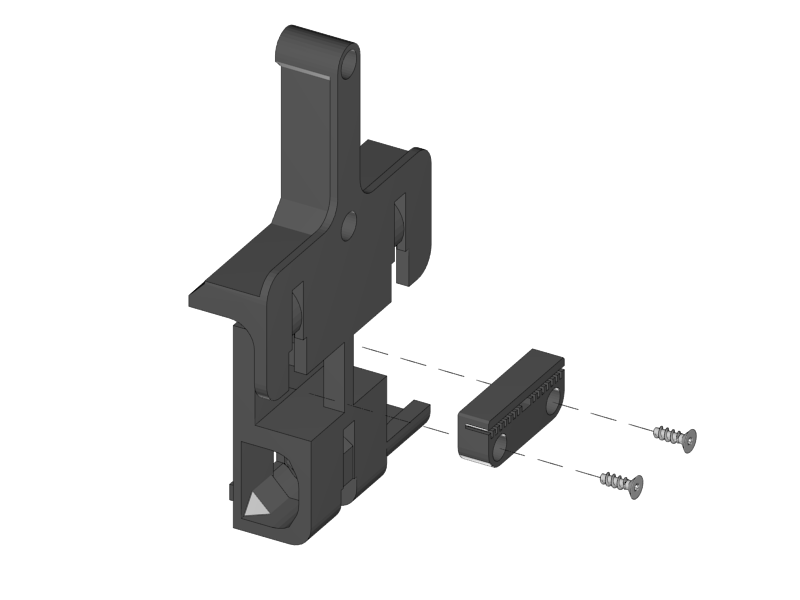
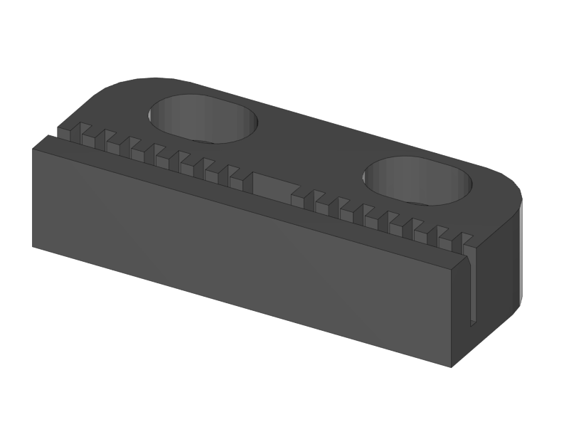
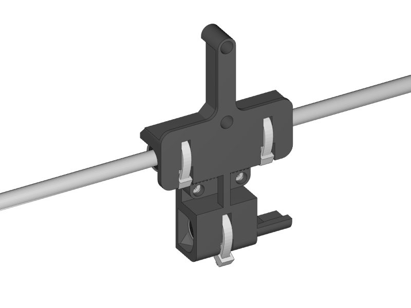
Mount the endstop with its cover onto the X-Motor assembly.
-
Don’t make the screws too tight.
|
|
|
-
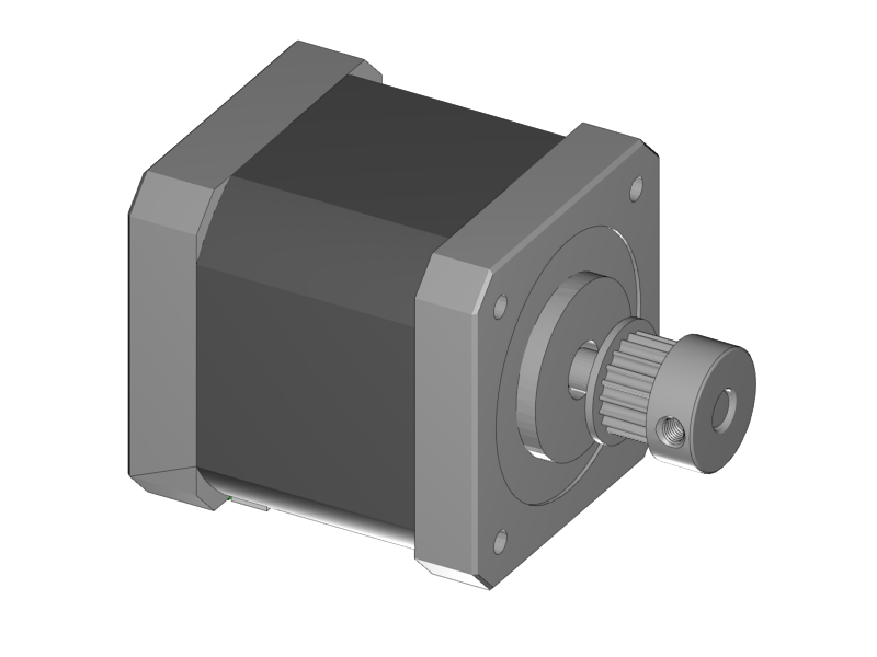
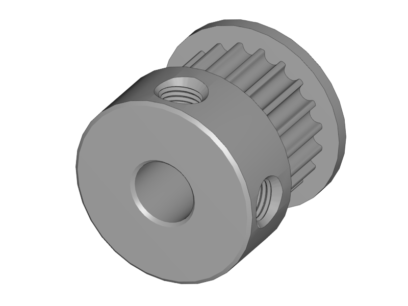
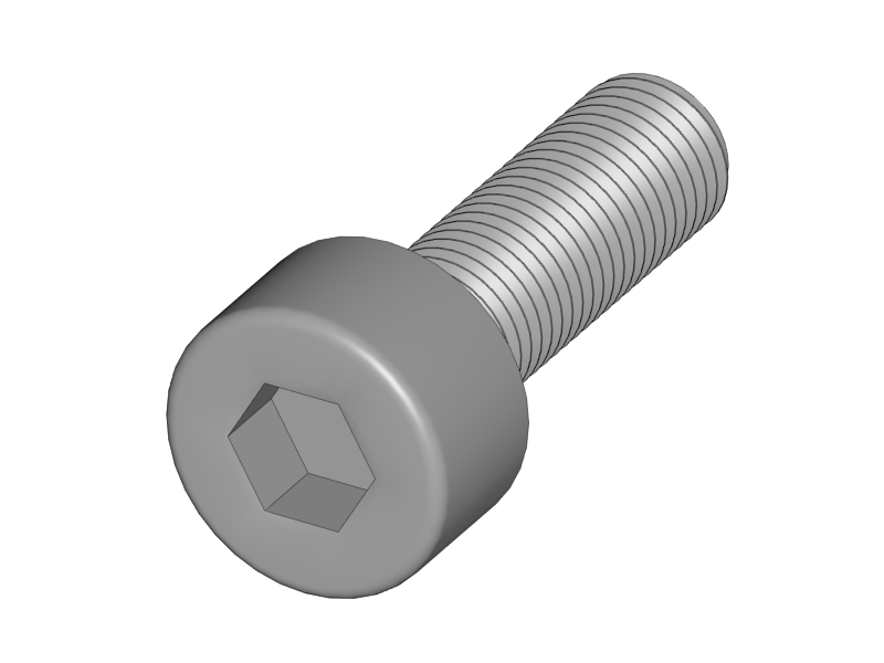
Mount the pulley onto the motor shaft.
-
Fix it with the two little set screws that you can find in the white bag in your RUMBA electronics box.
-
The distance between the motor and the pulley is 4.5mm.
|
|
|

-
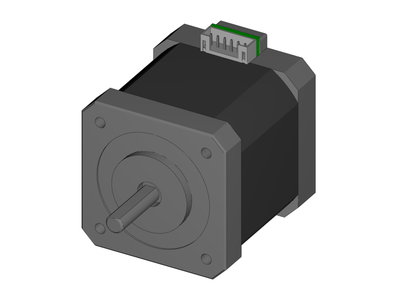
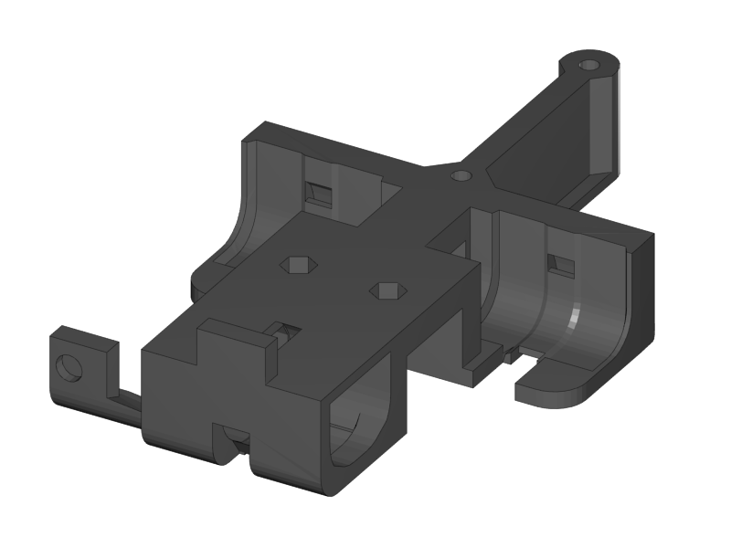
Mount the motor onto the X-Motor holder.
|
|
|
|
|
|
|
|
|
|
|
-
Put the linear bearings onto a smooth rod
-
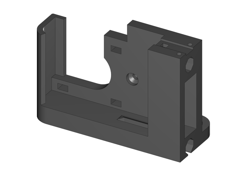
Put the linear bearings with the smooth rod into the pocket for the bearings
-
Put the ACME Nut in position
-
Place the bearing holder
-
Fix it with two M3x16 Torx screws
-
Remove the rod
-
Note: the bearings can move left and right a couple of millimeters (with some friction). This is to avoid load on the bearings that can be caused by tolerances in the length of the linear rods of the X-Axis.
|
|
|
|
|
-
Pierce the holes in the X-Carriage.
-
The hole is closed of with one print layer for good print results. You can easily pierce it by pushing with a small allen key or screw driver from the other side.
-
-
Slide the X-Teeth into position
-
Fix the teeth with the screws.
|
|
|
|
|
-
Place the upper two bearings into their slots
-
Slide a smooth rod through the bearings
-
Mount the upper two bearings with a ziptie. Mind the orientation of the head.
-
If you don’t have a big ziptie, fix it with TWO small zipties for better stability.
-
-
Remove the smooth rod
-
Push in the lower linear bearing
-
Mount it with a ziptie.
|
|
|
-
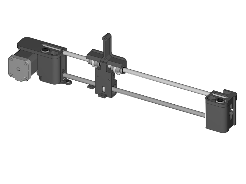
Slide the long (400mm) smooth rod into the upper hole of the X-Motor holder
-
Make sure it reaches to the end.
-
If it goes too stiff you can put the end into a hand drill. Do not use a hammer.
-
-
Slide the short smooth rod in the the X-Motor holder
-
Slide the X-Carriage assembly onto the rods. Mind the orientation!
-
Slide the X-Idler onto the smooth rods. Again make sure that they reach until the end of the hole.
-
If it goes stiff make a light twisting movement with you hands while you push the plastic parts more and more together.
-