-
Notifications
You must be signed in to change notification settings - Fork 20
Section 3.4 Assembling the Extruder
|
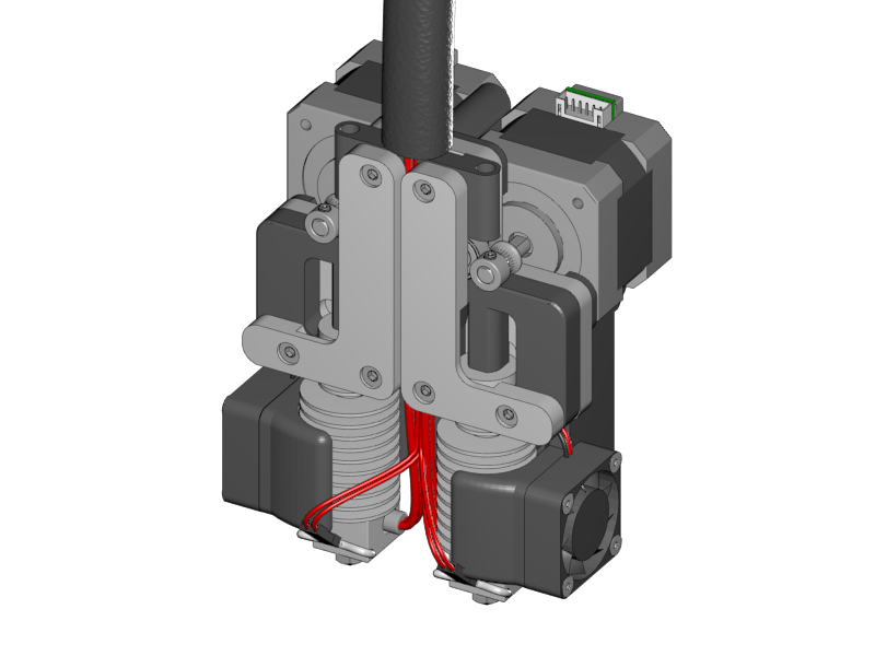
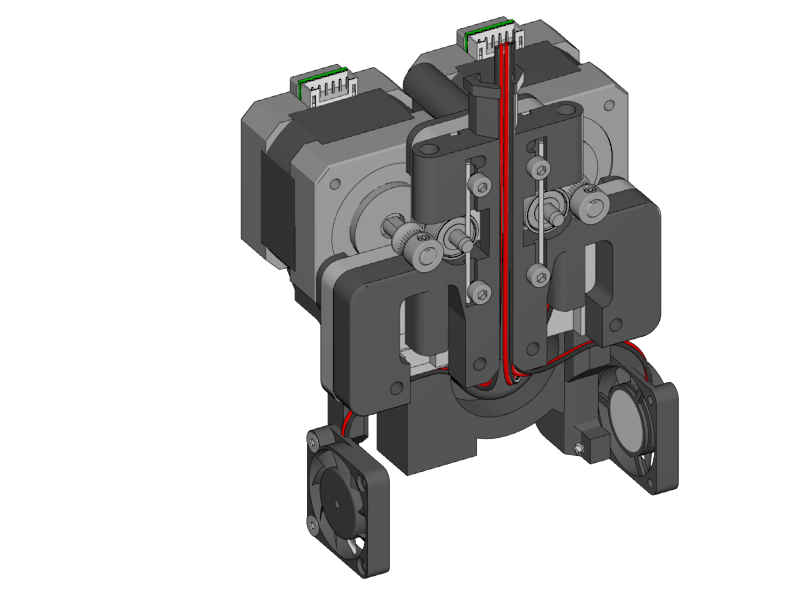
Finally it is time to build the extruder. The design of the extruder is made to be a dual extruder, but you can also make it a single extruder by leaving out the right hand motor and hotend.
|
|
|
|
|
-
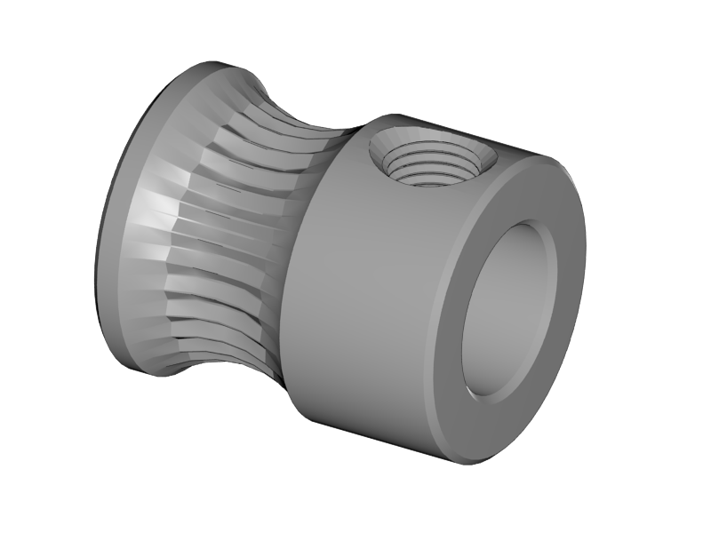
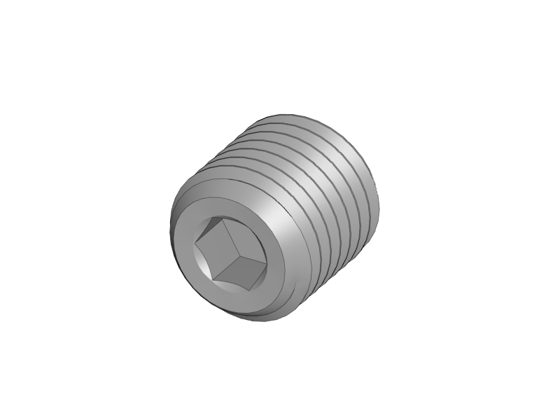
Turn the set screw into the filament pulley
-
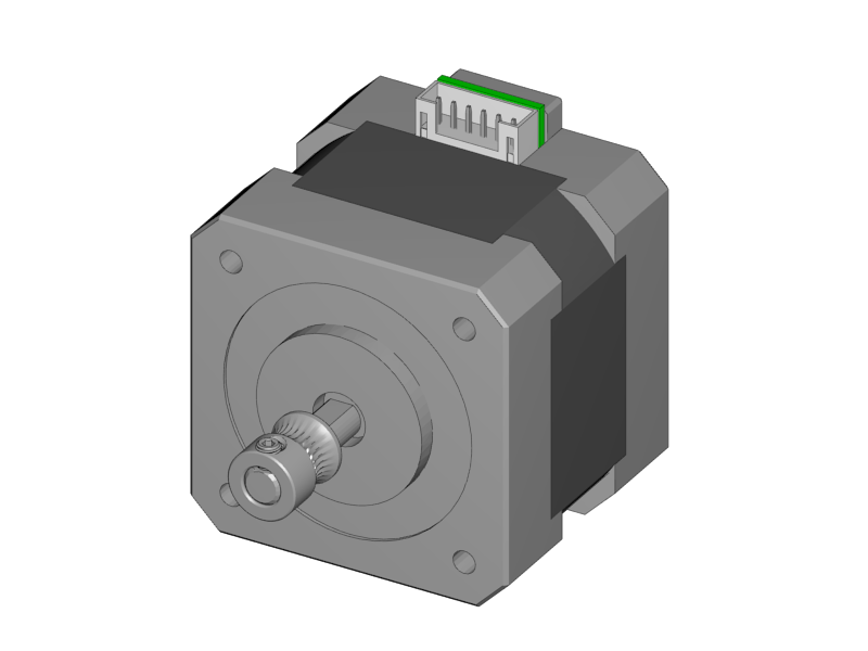
Fix the filament pulley onto the motor shaft
-
Make sure that:
-
The screw is on the front
-
The screw touches the flat side of the motor shaft
-
!!! The front of the pulley and the motor shaft are not flush ( we got new motors with a longer shaft picture is not updated yet), once the extruder is assembled you can use a piece of filament to adjust the pulley to be in the right position. !!!
-
-
For a dual extruder, prepare two motors
|
|
|
|
|
-
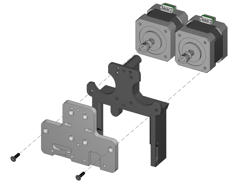
Mount both motors onto the fan holder and base plate
-
Make sure the motors are straight and tighten the screws well
|
|
|
|
|
-
Make sure the filament path is free. Test it with a piece of filament.
-
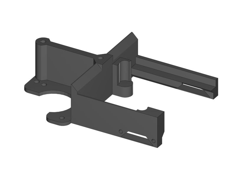
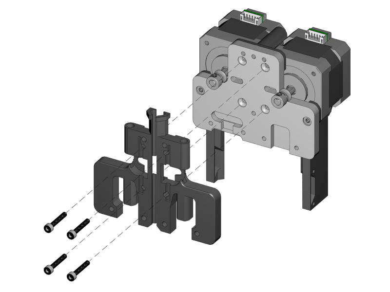
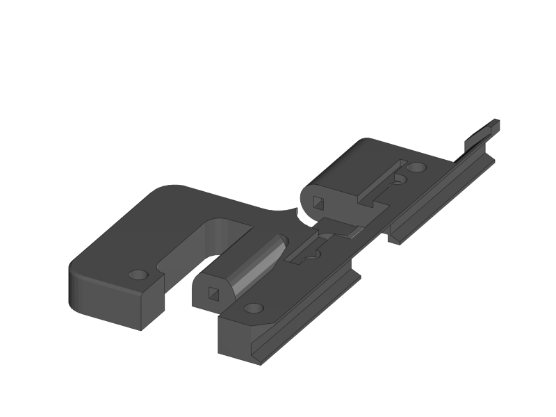
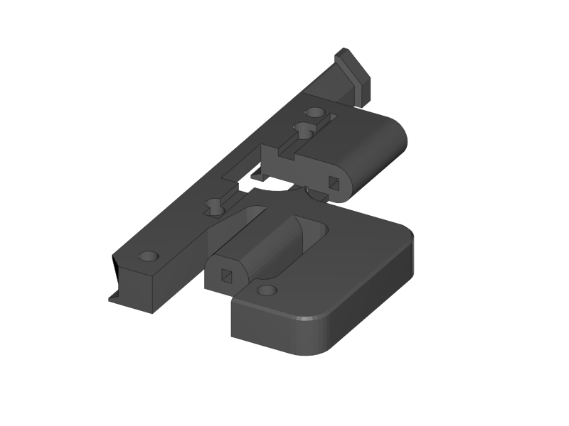
Put the plastic parts onto the assembly, but do not tighten the screws yet
-
For single extruder put the right plastic part later, and fix it with the aluminium plate
|
|
-
Slide the extruder springs behind the plastic part.
-
Push them all the way in, with the aid of the other extruder springs.
|
|
|
-
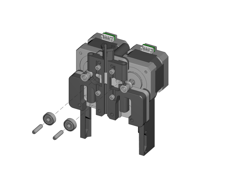
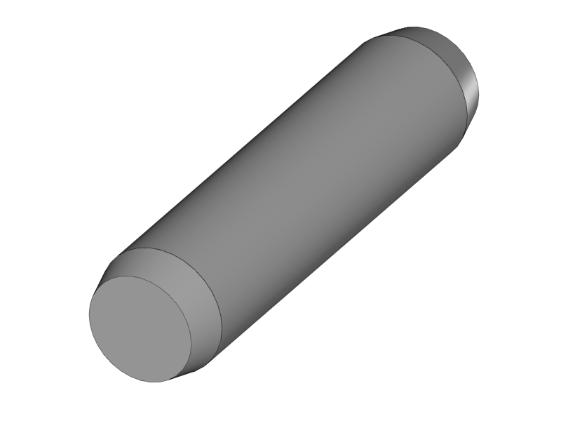
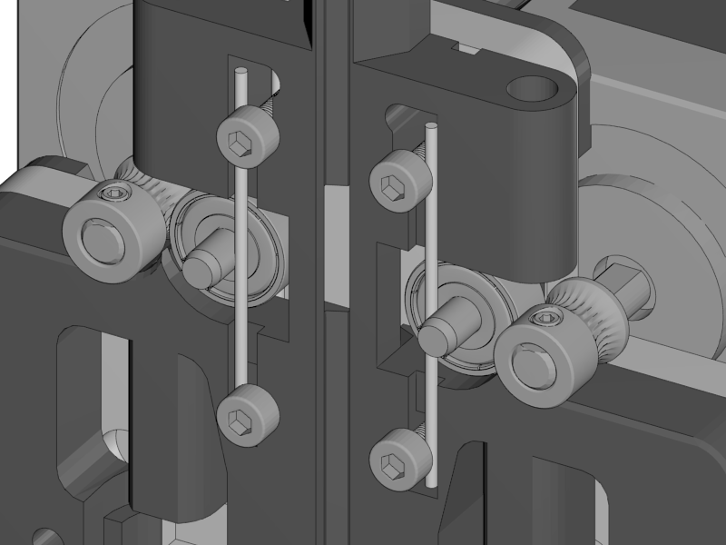
Put the dowel through the bearing
-
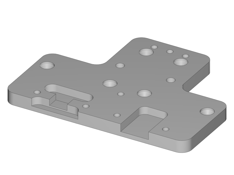
Place it into the slot hole of the aluminium base plate
-
Repeat for dual extruder
|
|
-
Slide the remaining two extruder springs behind the heads of the M3x20 screws
-
Tighten the screws (but not too tight!!)
-
The ball bearing is (almost) touching the filament pulley
-
|
|
|
|
|
-
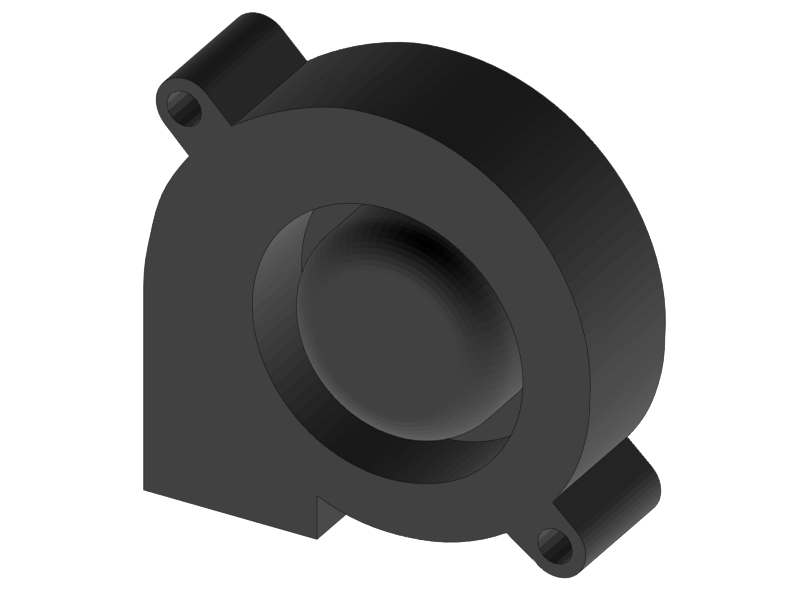
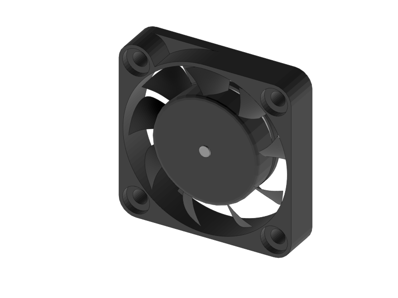
Click the radial fan into the designated slots of the extruder fanholder part
-
Lead the wire through the cable channel
-
-
Mount the fans onto the extruder fanholder
-
Make sure the wires for the fans are soldered so the fans are powered with 1 connector
-
Lead the cables through the cable channel
-
|
|
|
|
|
|
|
-
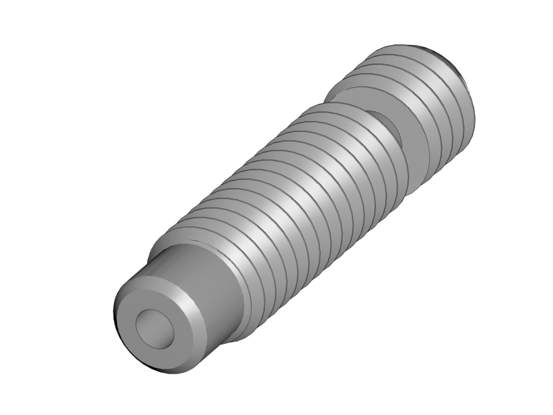
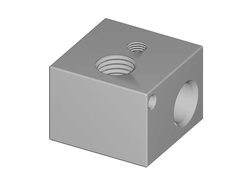
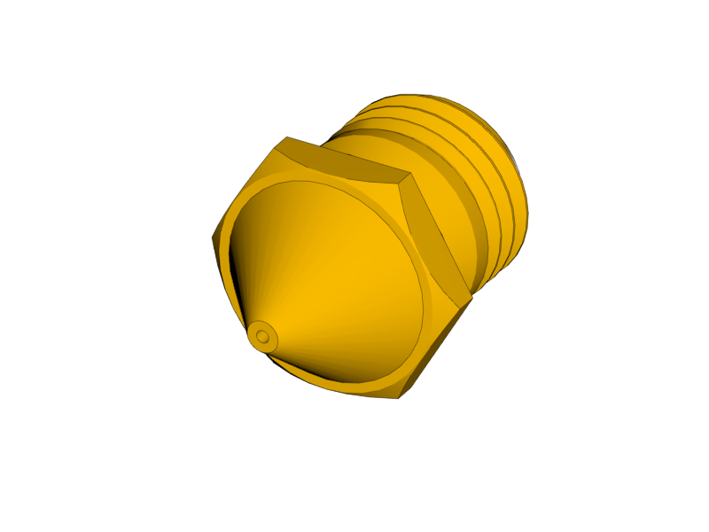
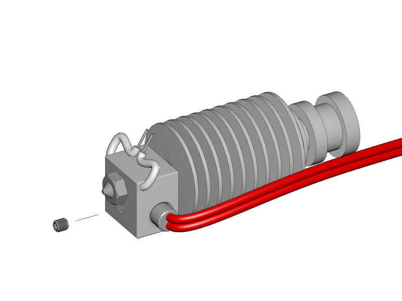
Screw the Heatbreak and the nozzle into the Heater Block
-
Handtight is well enough
-
there might be a teflon inliner , do not put it in yet
-
-
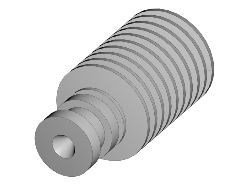
Screw the cooler body onto the Heatbreak
-
Make it tight, but only hand tight
-
Understand that the heatbreak has a very thin 'neck' which can be damaged with too high force
-
|
-
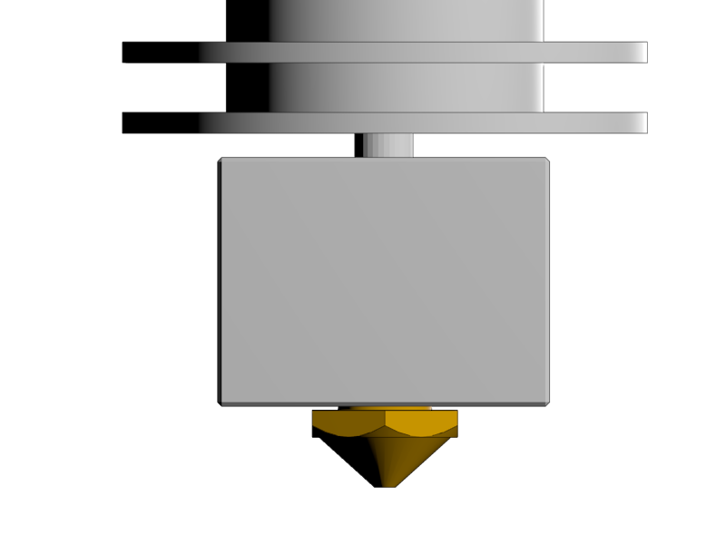
Adjust the nozzle in such a way that there is just a couple of tenths of a millimeter between the heater block and the head of the nozzle.
-
The neck of the heat break should be more or less flush with the top of the heater block
-
Everything is fixed, but only hand tight
-
Later the nozzle will be fixed while the hotend is heated to 300°C. This is to make sure the nozzle is press fit to the heat break
-
Fixing the nozzle like this also reduces mechanical load on the heat break while fixing the nozzle
-
|
|
-
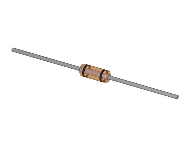
Put a piece of heat resistant insulation on both legs of the thermistor
-
Leave about 5mm of blank metal for connection
-
|
|
|
-
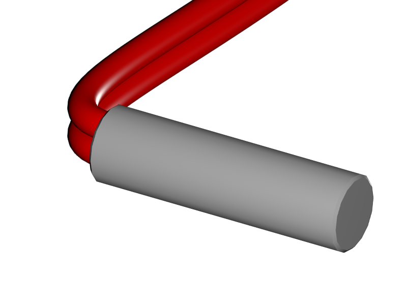
Slide the heat cartridge into the hole of the heater block
-
The left side of the cartridge should be flush with the heater block
-
Gently fix it with the set screw
-
In a dual set up the cartridges are mirrored. Use the picture of the next step as a reference
-
-
Slide the thermistor into the little hole
-
Make sure the thermistor is (more or less) in the middle
-
Bend the leads so it cannot slide
-
Bend the leads together so you can connect it later with a connector.
-
|
|
|
|
|
|
|
|
|
-
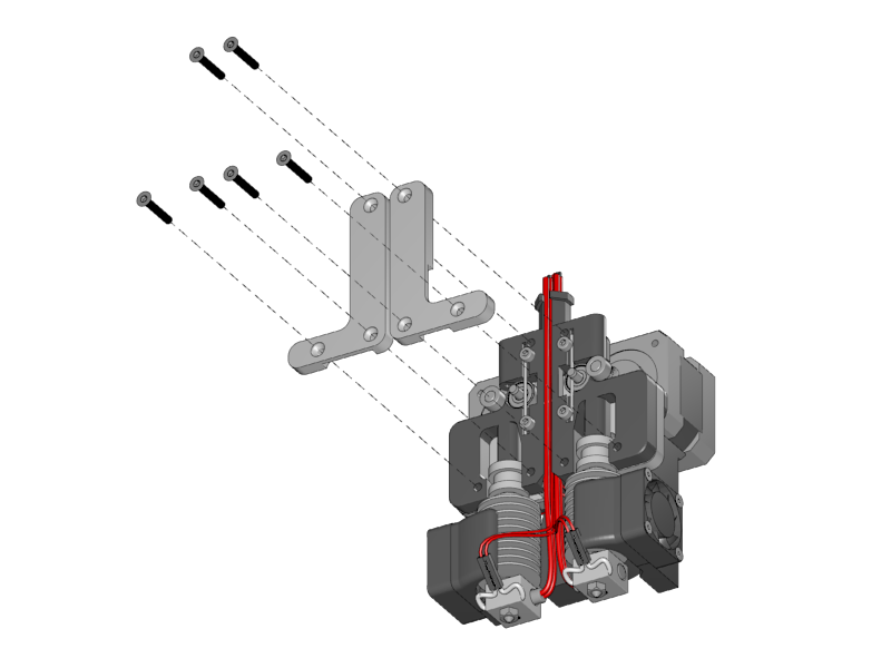
Put the hotends onto the extruder base plate
-
Connect the thermistors. Polarity is not important
-
Lead the wires through the wire channel
-
Lead the wires of the heat cartridges through the wire channel
-
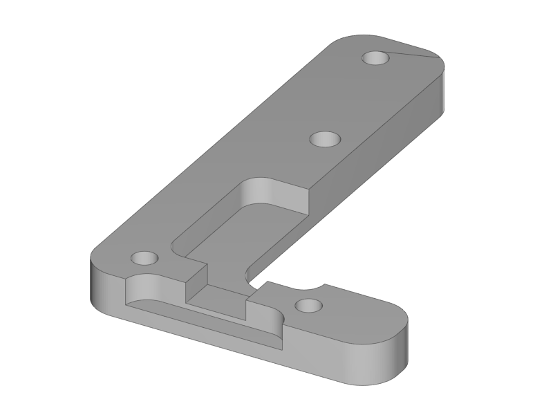
Fix the hotends with the aluminium front-plates
-
The right hotend can slide some millimeters in it slot.
-
Mount it as far up as possible. The exact height will be adjusted later.
-
-
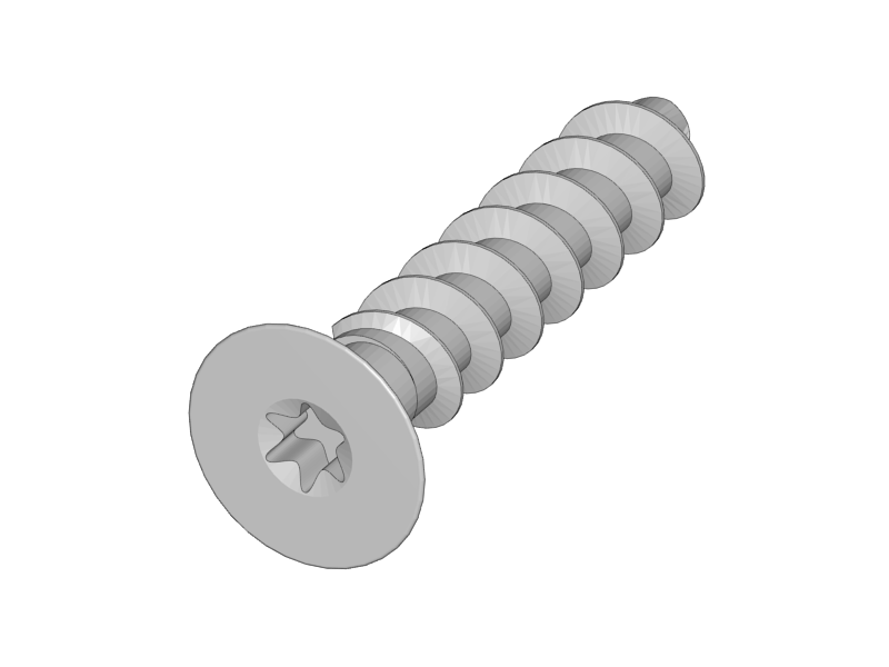
Mount the fan duct in front of the hotends with the torx screws
##i3 Berlin
1 Introduction
1.1: History
1.2: Tools and Parts
1.3: Preparing the Casings
2 Assembly of the Y-Unit
2.1: Rods and Power Supply
2.2: Front- and Back- Plate
2.3: Mounting Y-Carriage and Belt
3 Assembly of the XZ-Unit
3.1: Mounting the X-Axis
3.2: Mounting the Z-Axis
3.3: Mounting the Timing Belt
3.4: Assembling the Extruder
4 Wiring
4.1: Wiring the Power Supply
4.2: Wiring the Z-Unit
4.3: Wiring the Y-Unit
4.4: Wiring the X-Axis
4.5: Gluing the Endstop Magnets
4.6: Uploading Firmware
4.7: Wiring the Extruder
4.8: Mounting the Heatbed
5 Calibration
5.1: Testing Functionality
5.2: Calibrating the Y Axis
5.3: Calibrating the X Axis
5.4: Calibrating the Print Platform
6 Printing
6.1: Filament Holder
6.2: Cura
6.3: Kisslicer
6.4: Dual Printing
